Facebook
 Google
 GitHub
 Linkedin
The Mechanic’s View of Control: Types of Gear Drives
Although electrical systems often receive the highest praise for advancement, precision, and technological innovation, the world would be stuck without mechanical power delivery systems like gear drives.
Many engineers in the fields of control and automation can trace their roots to an education or background in mechanical fabrication. Perhaps it was a shop class, a mechanical engineering degree, or a life of working on farm equipment, but along the line somewhere, a love for machinery, motion, and control came together for an exciting career in automation.
Mechanical systems do not tend to advance as rapidly as electrical controls and networking, especially in the past several decades. Every once in a while, a new material or fabrication process opens the door to new innovations, but most mechanical power transmission systems and machines have remained largely the same for many generations.
In looking at mechanical drive components, one of the most exciting and intriguing is the gear. Most of them are not, by themselves, very complex, but when assembled into compounded gear trains with changes in size, speed, and angle, the results can lead to some amazing technology. Here are some of the fundamental concepts of gear drive applications and the various designs that allow geared motion.
Application of Gears
Since they are a power transmission system, we find gears used mainly when rugged, fixed shafts must be driven at a relatively close distance to the motor. They also work well when speed is highly dynamic, as compared to many rubber belts, which work well at high speeds only.
Transmissions, of course, are one of our most familiar examples of geared control, although we rarely get a glimpse inside a vehicle transmission.

Figure 1. A fairly simple 6-speed transmission with additional reverse. The shift fork engages only one spur gear pair at a time.
Gearboxes on motors can slow down motor rotation while increasing the torque tremendously, and many companies specialize in motor-compatible gear products.
Some gearboxes appear to simply extend the shaft (same concentric axle as the motor) but contain an internal ‘planetary’ arrangement that increases output torque in a small space.
Types of Gears
Rather than provide a bullet list of the hundreds of subtle variations by name, we will examine the end objective of gear drives and discuss which devices have been developed to meet each need.
Offset Axles
The most common type of gear train includes parallel shafts, where the motion input rotates around one axis, and the output is a short distance away, or even along the same axis, but is disconnected from the input.
This disconnect from input to output can provide advantages of higher speed or output torque, but it’s important to remember that gears can never increase power, no matter the efficiency. You can get higher speed or higher torque, but not both. Gears are really cool, but they are not magical.
There are several common types of gears in this category.
Spur Gears
The spur gear is perhaps the most common of this subset. Straight teeth cut across a blank disk mesh with similarly-sized teeth on a mated gear. The disks do not need to be the same size (radius, diameter, or thickness), but the teeth do, otherwise, they will bind quickly and fail to spin.

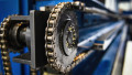
Figure 2. A big old spur gear. I’m sure there are bigger ones out there, but this is the biggest one I’ve ever owned.
This is a great, simple system, but one disadvantage appears when closely examined, the faces of each pair of teeth are not in constant contact. That means that while spinning, there is a small gap before each new set of teeth engages, resulting in noise, loss of energy, and, if stopped, an ability for the output gear to move slightly while the input stays firmly fixed. Multiply this small angle change by a train comprised of ten gears, and the ‘slop’ in the output may be very severe.
Helical Gears
Helical gears are somewhat similar to spur gears, but the teeth are not cut straight across the face but rather at an angle. When viewed from the side, the angle of cut may be either positive or negative, and if both types (a + and a -) are joined together. The result will be parallel motion like a spur gear. However, if similar helix angle gears are meshed, the result is a change in the angle between the shafts, in addition to the offset distance. This configuration will be explored in a later section.
The benefit of the helical gears is that part of the tooth is always in contact with the mating tooth, and the next set will begin its point of contact before the previous tooth set disengages. This reduces the backlash (slop) in gears with a gap between teeth, and it also reduces the noise and energy loss.

Figure 3. The angular cut of the teeth allows these helical gears to function much like spur gears but with less slop and noise. Image used courtesy of Canva
It is very common to see all kinds of simple gears created with teeth cut at an angle in this fashion.
Angled Axles
If the shafts are located along the same plane but at an angle to each other, the above solutions will not work. To get an idea of what this means, hold both hands in front of your face with the tips of both pointer fingers touching. Now move one hand up and down or closer and away from you. Those fingers will always be in the same plane, but they form an angle right at the point where your fingertips touch.
Bevel Gears / Miter Gears
These gears are common for angle offsets at or near 90°, resembling a cone with the top removed (called a ‘frustum’ for you geometry nerds). The teeth, either straight or curved to increase contact continuity, are cut into the angled face.

Figure 4. A twin bevel (or miter) gear with a shift fork allows this simple transmission to shift from forward to neutral to reverse by engaging one bevel gear at a time.
If the gears are the same size, the only intent is the change the angle. If the gears are of different sizes, such as would be found in the rear differential of some simple rear-wheel drive vehicles, the output will be a different speed and torque.
The angle formed by these gears is the addition of the two angled faces of the frustum shapes. If both lie at a 45° angle from the ground, the total angle change is 90°. It is common for one of the gears to have an angle much larger than the other, but once again, the teeth must be the same size as both gears to allow proper meshing.
Offset and Angled Axles
If both an angle change and an offset are present, they are solutions.
Worm Gears
The worm drive is a common arrangement of a single helical gear aligned beside a shaft resembling a screw with large threads. In this system, the screw (worm) shaft is always the driver due to the massive contrast in tooth angle. The worm gear simply pushes the round-wheel gear. If reversed, the wheel is attempting to push on those same teeth, but instead of rotating them, it will simply try to push the axle. Almost like a one-way valve, or diode, for mechanical power.

Figure 5. In a worm drive system, the worm screw (bottom gear in this image) is always the driver, as any backlash may produce a lot of force, but the angle of the screw teeth is simply too low to create rotation. Image used courtesy of Canva
Since the diameter of the shaft is small compared to the round gear, the worm drive results in a massive increase in torque, with a similarly large reduction in speed. If a gearbox exhibits such a change, it is likely to have a worm drive inside.
Helical Gears
As mentioned before, when two similarly angled helical gears are meshed, the angle formed between them is a sum of the two individual angles. Since they are manufactured from a round blank, just like spur gears, they will have a linear offset, but the angled teeth provide an additional angle change. Most commonly, in this arrangement, they will both have 45° teeth, resulting in a 90° total angle change.
Gear Types
This is by no means a comprehensive list of gears, but it provides an overview of the main types used in equipment manufacturing for general industry. In following articles, we will discuss the mathematics of gears that allow them to transmit power while keeping energy losses to a minimum.