Facebook
 Google
 GitHub
 Linkedin
Tutorial: Driving Mecademic Robots with Siemens PLCs
Learn how to create programs that directly drive a Meca500 robot arm using a Siemens S7 PLC, including adding the hardware and using pre-built function blocks for STEP7 TIA Portal.
Most industrial robots are programmed on a teach pendant. The motion instructions are placed in a sequence, and the controller waits for digital signals or position variables from a PLC before starting the routine or proceeding to a subsequent step. In this model, the robot acts as the controller.
Mecademic’s small, precise robots operate under a different model. These robots accept signals over multi-protocol channels, taking direct motion variables and drive commands from the external PLC. In this sense, the PLC is the controller; the robot simply receives motion commands like a standard VFD or servo drive.
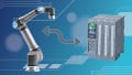
In previous tutorials, we have driven the robot from a Rockwell PLC environment over Ethernet. This time, we’ll explore an example program that drives the robot over PROFINET from an S7-1200 Siemens PLC.
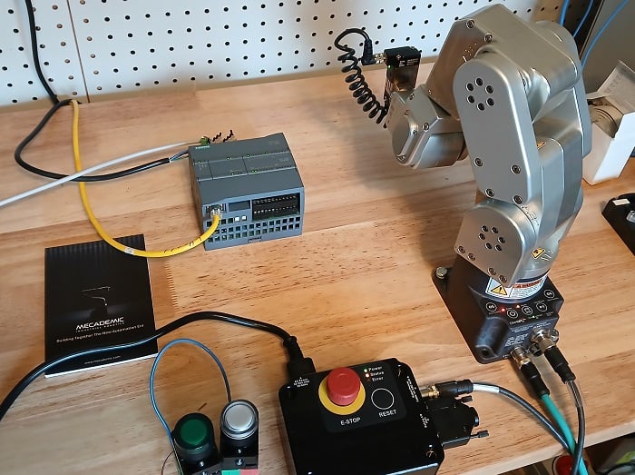
Figure 1. The project hardware.
Version Prerequisites
This project has some hidden version requirements. Due to startup conditions for the robot (it uses advanced startup, not legacy startup), the PLC firmware version must be 4.2 or higher. This means that the STEP7 TIA Portal version must be 14 or higher.
Hardware Setup
This project includes the PLC, the robot, and the computer.
The PLC uses several digital inputs, which can be provided via external switches or the handy I/O switch simulator board provided by Siemens (6ES72741-XF30-0XA0). We will get started with a pre-built project provided by Mecademic, and this project requires inputs %I0.0 and %I0.7. I recommend selector switches, not momentary pushbuttons.
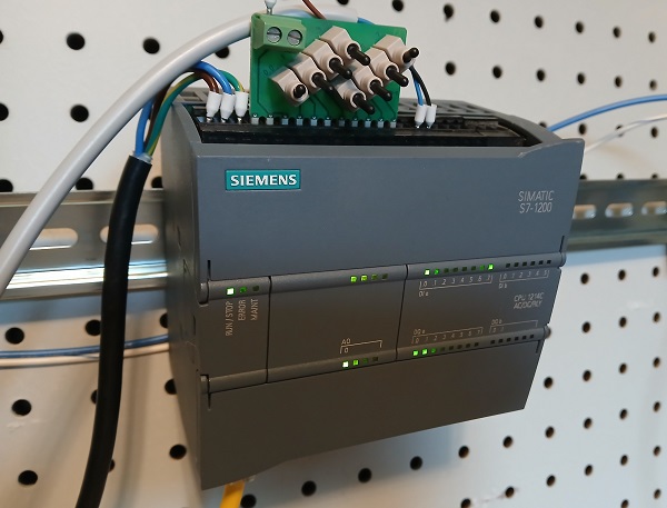
Figure 2. The PLC with the simplautor board and two additional pushbuttons.
The PLC is connected to an unmanaged switch.
The Meca500 robot and the PC are also connected to the switch. The PC must contain a web browser and TIA Portal (again, version 14 or above).
Activate PROFINET on the Robot
Before we can use the Siemens PLC to command the robot, we must activate PROFINET.
Open a web browser and type in 192.168.1.100, the web server for MecaPortal. If the robot’s IP address has been changed, use that address instead.
Make sure the robot is disconnected from any other PLC, then activate it and switch to ‘control mode’ in MecaPortal. In the top-left corner menu, open Network Configuration and enable Profinet mode.
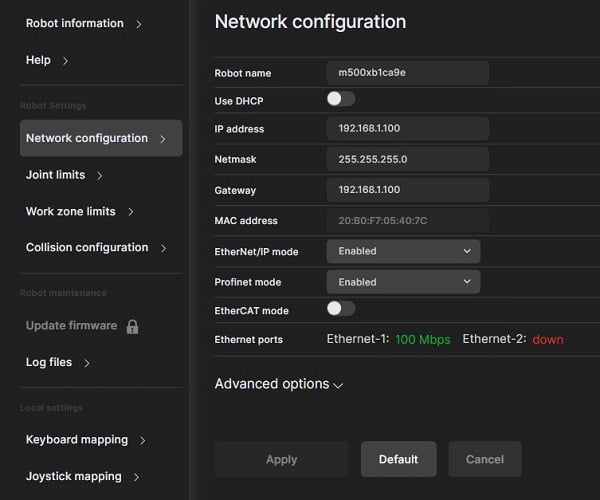
Figure 3. Activating Profinet mode.
You can now close the web server. It won’t be needed any longer in this project.
Project Elements
To use the pre-built project from Mecademic, we need to install the GSDML file for the robot and import the project into TIA Portal.
GSDML File
Download the firmware package; this zipped folder also contains the EDS, GSDML, and ESI files for various protocols. Extract the downloaded folder, open it, and then open the ‘protocols’ folder.
In the TIA Portal project, open Options -> Manage general station description files (GSD). Choose the folder path from that firmware folder and install.
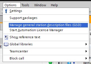
Figure 4. Installing a GSDML file.
PLC Project Code
Although we could design a project from scratch, there is no sense in re-inventing the wheel. It would be quite complex since the function library is very extensive.
This Siemens PLC integration page contains the library and example projects. For this intro, we will use the full project and make some changes. Scroll down and download “Meca500 V10.2 Siemens Demo.”
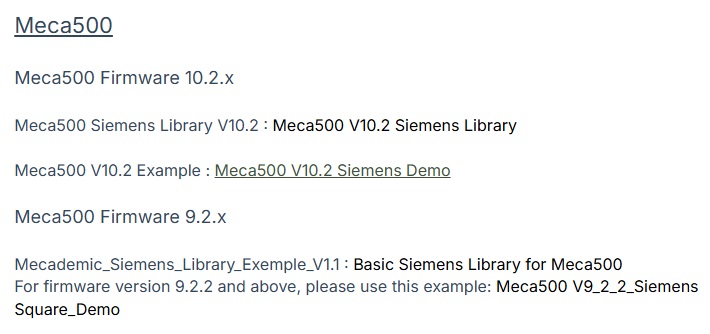
Figure 5. Project source file.
Opening and Downloading the Program
Open TIA Portal, then select and open the newly downloaded project file. It has a .zap16 file extension. I would suggest immediately “Save As” with a new name, just so you keep the original backup. I called mine Meca500Test.
Since this project already has the PLC and the robot added, the IP addresses will need to be verified before downloading. Double-click on Devices & networks in the project tree.
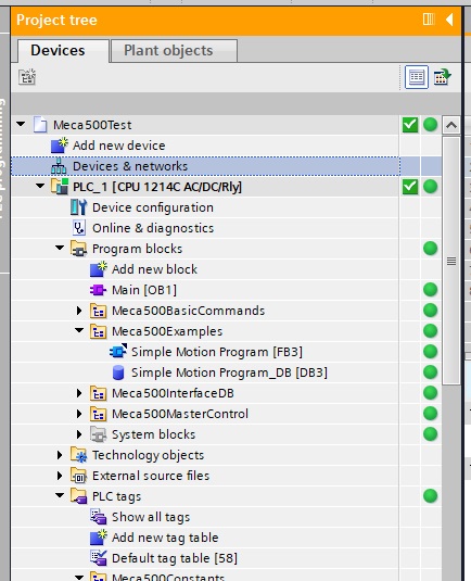
Figure 6. Accessing the project devices.
Next, double-click on each of the network ports one at a time and make sure the IP addresses match your actual devices.
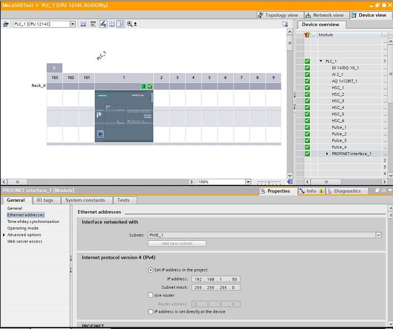
Figure 7. Editing device IP addresses.
Hopefully it should go without saying: make sure the PLC, robot, and computer are all on the same subnet.
At this point, you should be able to do an “Extended download to device…” to send the project to the PLC (make sure you click on the program blocks or tags, otherwise the download options will not be available).
At this point, the robot will actually move now, with just a couple flips of some switches. But first, let’s explore the program blocks.
Testing the Default Program Blocks
The Main program block contains only two networks. The first function, Meca500_Control, provides the connection and enabling of the robot. Activating digital inputs 0 and 7 should achieve this connection.
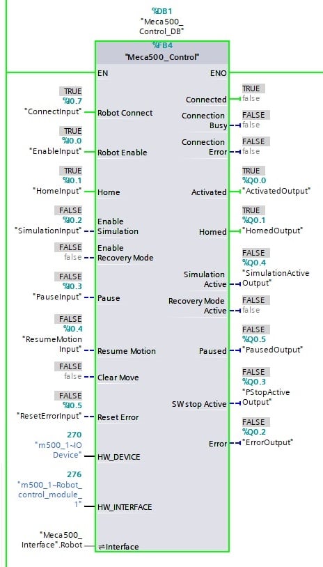
Figure 8. The necessary ‘Control’ function block.
The next network calls a simple motion program, which is a sequence of a few XYZ target point move commands.
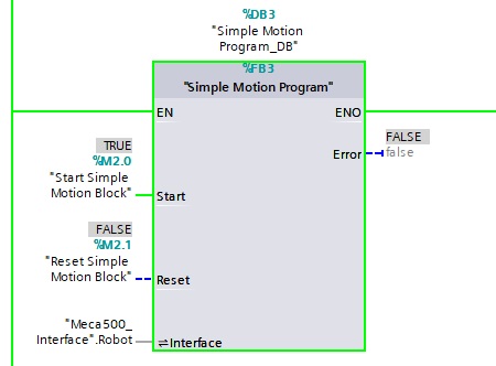
Figure 9. Default motion program function block.
To test the program: clear the area in front of the robot and modify %M2.0 to 1.
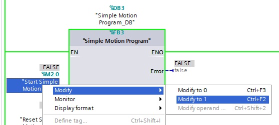
Figure 10. Running the default motion program.
The robot should make a few linear moves and return to a joint position of (0,0,0,0,0,0).
Create Our Own Code
This sample project will conclude with a simple 2-point program. Two pushbuttons: one button moves the robot to a position, the other pushbutton returns it to (0,0,0,0,0,0).
First, connect two new pushbuttons, since the main control block consumes nearly all of the switch inputs on the simulator module. I connected my new green and white buttons to inputs %1.1 and %1.2.
Create a new block under the Examples folder.
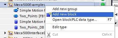
Figure 11. Adding a new function block.
Create a new Function Block (FB) and call it ‘Two_Points.”
This function block will require a few input and output variables, because they are fed into the Move functions.
Two_Points FB:
Inside this new function block, populate it with the following variables:
Error, Interface, Sent, and Buffered. Note the category and data type for each one.
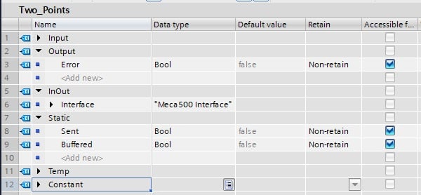
Figure 12. Function block variable list.
Next, we can add the move functions to the ladder networks. The first rung will use the green button input to drive the robot back to the zero position, so we will use a MoiveJoints function. Add the input and output variables as shown below.
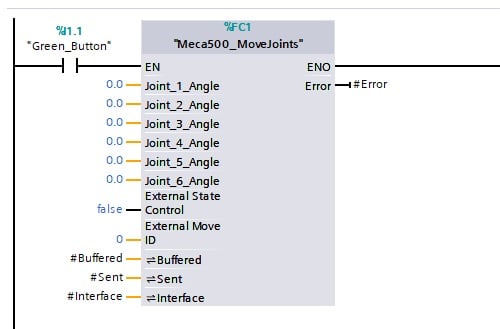
Figure 13. First motion instruction.
Next, we’ll add a linear move command to the next rung, driven by the white button. The positional values are arbitrary, but be sure to choose a position that is A) reachable, and B) does not collide with objects in your workspace.
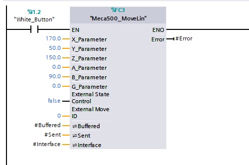
Figure 14. Second motion instruction.
Main OB:
The final step is to add a call to this function block in the Main routine. There is no need to remove the original example program call; this one can be added in the next rung. Adding the function block will prompt for the creation of a new Data Block for the I/O variables. Add the “Meca500_Interface”.Robot interface input.
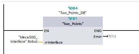
Figure 15. Calling the new function block.
Download this new program to the PLC, and the green/white buttons will drive the robot between these positions.
For next steps, you can add MoveGripper and Set…Vel (velocity) for joints and linear moves to obtain more precise control over the program.
Conclusion
With this project, we now have a template function for either a sequence of steps or for a directly driven set of point commands. If your PLC is able to calculate the positions from a system or other inputs, it can directly drive the robot.
This is a bit of a shift in mindset for traditional robot programmers, but in terms of integration, it’s simpler because all of the programming is completed outside of the robot! Perfect for getting the entire control system project running and verified before installation.