Facebook
 Google
 GitHub
 Linkedin
Tutorial: Driving a Mecademic Industrial Robot with a Rockwell PLC
Learn how to drive a compact Meca500 industrial 6-axis robot with a CompactLogix PLC over an Ethernet connection, transferring direct TCP set points in joint and world coordinate systems.
There are several ways to program industrial robots, each one custom-designed for certain applications and levels of user involvement.
The most common are to use a teach pendant or hand guidance to navigate the robot to key locations, save those locations, and then cycle through them, interspersed with end-of-arm tool commands.
Another method to explore today is using a PLC to supply all target points and gripper commands. Instead of the robot being the controller, the PLC is the controller; all robot motion is accomplished through the use of function blocks in the ladder code.
In this example, we will use an Allen-Bradley CompactLogix PLC to drive a Mecademic Meca500 robot arm, which allows motion commands over Ethernet/IP.
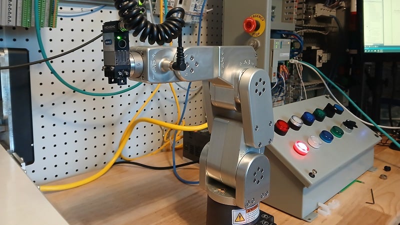
Figure 1. Run a Meca500 robot from a Rockwell PLC.
This tutorial assumes that you have already set up the Meca500 robot and become familiar with the 6-axis programming interface in the MecaPortal web server. Please review that tutorial here.
Process Summary
This integration guide will walk through the following steps in order:
- Set the IP address of the robot and enable Ethernet/IP.
- Locate and install the EDS and import the AOI into the Studio 5000 PLC environment.
- Create a new instance of the robot in the hardware configuration of the PLC project.
- Send function block commands to control the robot.
Set the IP Address of the Robot
Since this new robot will be added to the PLC hardware configuration, it must be in the same subnet as the PLC. It is helpful if the programming laptop is also on that same subnet.
In the MecaPortal, access the menu in the top-left corner and select Network Configuration. You must be in control mode to access this menu, which means that the robot cannot be currently connected to another PLC.
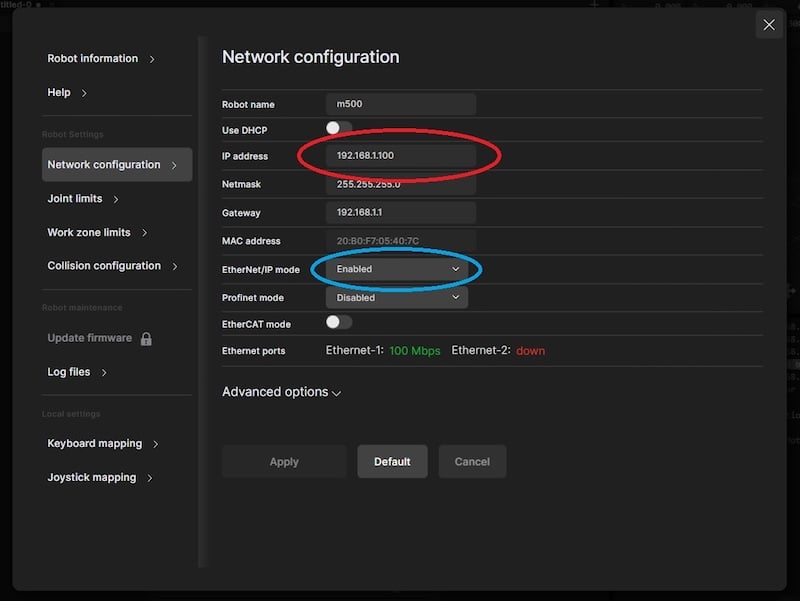
Figure 2. Set the robot IP address (red) and enable Ethernet/IP (blue).
In the network configuration menu, change the IP address, subnet mask, and gateway as needed to match the subnet of the PLC. Next, enable EtherNet/IP to allow the PLC to take over the robot. The robot is not simply listening to the PLC for triggers to run a program, but waiting to receive any motion commands at all.
In the connection mode menu, switch to monitor instead of controling.
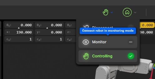
Figure 3. Activate Monitoring mode.
This step is important because in the PLC, we can choose whether to run the robot from the PLC or from MecaPortal. If the commands should come from the PLC, you must switch to monitor first. If the commands should come from MecaPortal, then switch to controling.
Install EDS and AOI into the PLC
Moving to the other equipment, we must prepare the PLC for its connection to the robot.
First, download the EDS file. The file can be found inside the firmware download folder. You do not need to update the firmware, but be sure that you are downloading the proper file for your robot’s current firmware. You can verify the robot’s current firmware in MecaPortal -> menu -> Robot Information. Install the file using the EDS hardware installation tool.
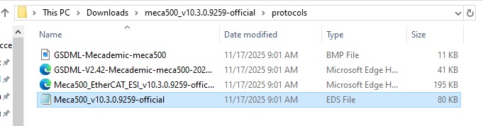
Figure 4. Downloaded folder location for the EDS file.
Next, we must import the add-on instruction (AOI) to ease the communication between devices. The AOI is found on Mecademic’s own software reference page. Be sure to use the Meca500 robot, and for now, we only need the AOI file that matches the firmware of the robot in our project, since the EDS file determines the data types used in the instruction.
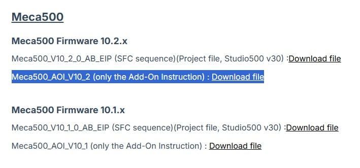
Figure 5. AOI for the Meca500.
Note: As of the time of writing, the robot and EDS version was 10.3. The most recent AOI was 10.2. If the EDS version and the AOI versions do not match, check out the fix at the end of this article.
Add the Robot to the Project
Right-click on the Ethernet adapter in the controller organizer of Studio 5000 and add a new module while offline. Add a new Meca500 and use the IP address that you supplied in the first step.
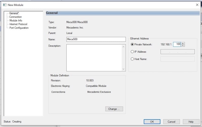
Figure 6. Add a new robot to the Studio 5000 project.
Whatever name you choose for the robot will be used in the motion commands later, so if you plan to use multiple robots, name them properly for the sake of project organization.
Download the new configuration to the PLC, go online, and the PLC should recognize the robot with a steady I/O OK light.
Driving the Robot With the PLC
Now that the PLC is in command of the robot, we can activate and run a very simple command set.
The general outline will go like this: ensure that control is via the PLC, activate and home the robot, then send a few x, y, z, w, p, and r coordinate move commands.
Let’s set up the commands first, so that they can be downloaded to the controller before starting the robot.
In the first rung of the program, drag in a Connect FB from the Add-On instruction tab. Right-click and add a new Connect tag. I named mine simply ‘Connect’. Choose the name of the robot instance that you want to control. Add a new Bool tag for the other Connect tag. When this tag is set to 1, the PLC will be in control. If the tag is 0, the PC will be in control.
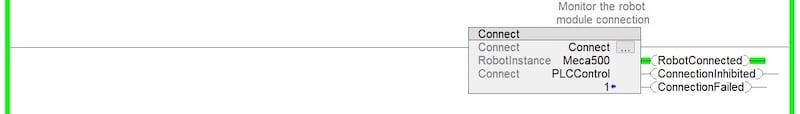
Figure 7. Connect instruction.
In the second rung, add a MovePose command with a digital input. This example will simply move the robot to this point when the input is energized. You may calculate the coordinates with CAD data, calculations, or by jogging in PC control. I used the position of (0, 190, 308, -90, 0, 90). This is a simple rotation of the base joint by 90 degrees.
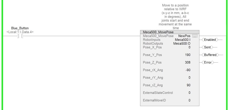
Figure 8. MovePose instruction.
In the third rung, add a MoveJoints block with all joint values equal to zero. This is the same as zeroing the robot, but added as a command block. Allow this rung to run when another digital input is energized.
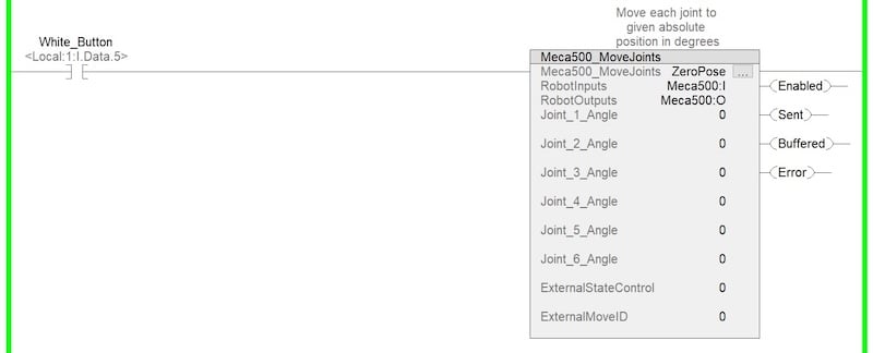
Figure 9. MoveJoints instruction.
Run the Program
Power on the PLC and the robot. Go online with the PLC and press the reset button on the robot safety controller. As mentioned before, but just in case it was missed, go to MecaPortal and ensure the robot is in monitor mode.
Navigate to the Connect FB in the ladder logic and change the Connect tag from 0 to 1. RobotConnected should illuminate green.
Go into the controller tags and open the Meca500 Output tags, energize first the ‘Activate’ tag, then the Home tag, then reset both to zero. The robot should make some small movements.
Activate the digital input attached to the MovePose command, and the robot should move. Then activate the input for the MoveJoints zero command, and the robot should move again.
You have now run a very basic set of motion commands. More complex motion paths are simply a sequence that contains more of these same motion commands.
Great job, you have driven a Meca500 robot!
Editing the AOI
These three things must match: the robot FW version, the EDS version, and the AOI version.
If the AOI does not match the robot and EDS version, there will be a problem importing because the data types do not match. To fix, install the EDS and import the AOI, ignoring warnings in this second step.
After importing, look into the module-defined data types. _061D:Meca500_xxxxxxxx:I:0 and _061D:Meca500_xxxxxxxx:O:0 refer to the current data types provided in the EDS.
Now, look at one of the add-on instructions, for example, Meca500_Delay. Open the Parameters and Local Tags.
The two tags RobotInputs and RobotOutputs are defined by the AOI version. Look in the Data Types column, and the xxxxxxxx numbers may not match. This same tag appears in many of the AOI instructions.
Open the Replace utility in the search menu. Expand the Find Within field and select Type.
- “Find What”: the old data type that currently exists in the Parameters and Local Tags of the AOI instructions.
- “Replace With”: The new data type as it appears in the Module-Defined Data Types folder.
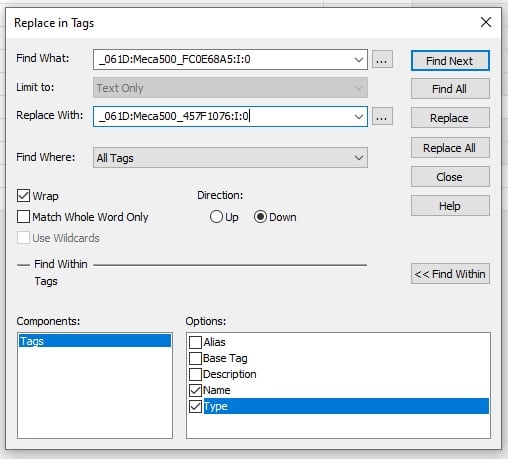
Figure 10. Replacing the old data type with a new data type.
My solution is shown above. Replace all instances, then download the program, and the errors should resolve.
All images used courtesy of the author.