Facebook
 Google
 GitHub
 Linkedin
A New Way to Robot: A Teach Pendant Feel With Structured Text Language
Meet the Meca500 6-axis arm, a robot known for its ultra-high precision and compact footprint. Learn how to use the web server for programming and 6-axis jogging with a structured text interface.
Recently, I was privileged enough to make use of the generous loan of an innovative robot, the Meca500 from Mecademic. In the past, I have programmed many 6-axis robots from manufacturers like FANUC, Yaskawa, Denso, and others. This robot from Mecademic provided some great new insights, both in terms of its programming interface and in its interaction with PLCs.
This robot is unique in its small size, but it has incredibly precise handling. The resolution is down to 1 µm and 5 µm of repeatability. It’s designed for high-precision applications like optics, medical devices, and pick-and-place assembly of fine objects.
Follow along as we explore the initial setup of the robot. Later, we’ll check out specific use cases for programming and PLC interaction.
Initial Robot Setup
If you’ve ever set up a 6-axis industrial robot in the past, you know that there are three major components: the robot itself, the control cabinet, and the teach pendant. The controller might live well outside the safety enclosure, away from the robot, and another long cable allows the teach pendant also to be located far away from the controller.
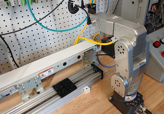
Figure 1. The Meca500 contains all the drive electronics in the base.
In contrast, the Meca500 contains all of the drive electronics (the controller) in the base. There is a separate box that connects the robot to AC line power, as well as an access point for an e-stop button and other safety inputs. Further, the Meca500 doesn't use a teach pendant. Instead, it uses an Ethernet connection and a built-in web server, so that any computer on the local network becomes the programming interface.
Setting up Hardware
All of this information is also found in the setup manual on the Mecademic website; this tutorial will explain the steps and add extra notes from a user perspective.
First, unpack and attach the robot to a firm base. If the arm is extended too far in any direction, it will tip over.
Before connecting the plug to the power outlet, connect the safety and power supply box to the robot base. Also, connect the safety circuit or attach the dongle included with the robot. This dongle bypasses the safety circuit, to be used only in prototyping or in a safe learning environment. Finally, connect the network cable from the robot base to the programming PC with a web browser.
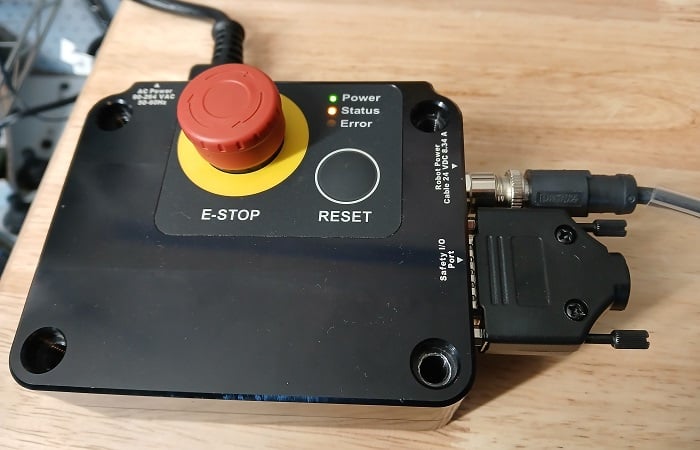
Figure 2. The power supply and safety I/O control box.
At this time, do not connect any end-of-arm tooling because, at first power-up, the robot must home. If the end effector is installed in the incorrect position, it may run into the robot and cause damage. Instead, wait until the robot is powered and homed. Then, the end effector can be installed later while the robot is powered off.
Powering up the Robot
After the hardware is connected, plug in the power cord to the 120 VAC socket and press the power switch on the safety control box. Press the Reset button on the control box, and the lights will activate on the robot base and begin blinking.
Over on the programming PC, set your IP address to a matching subnet with the robot. By default, the IP address of the Meca500 is 192.168.0.100. Once the robot and the PC are on the same network, you can access the MecaPortal web server by entering the robot’s email address into Google Chrome or another browser.
At this point, if you cannot access the web page, there are a few things to check:
- Is the computer indeed on the same subnet? If you do not have a robot fresh from the factory, it may have an edited IP address. You can use various IP explorer software to sniff out any devices connected to your computer, even on a different subnet. There are many such software available (I use one called “Ethernet/IP Explorer & C# Stack”). Pressing and holding the Power button on the base during power-up will reset the robot network configuration.
- Is the robot properly powered on? For a quick diagnostic check, examine the LEDs on the robot. The Power LED should be solid red, and the Link/Act IN should be solid green.
- Is the power box supplying power to the robot? The dongle or safety circuits should be connected to the Safety I/O port, and the E-Stop button should be released.
Jogging the Robot
For the scope of this article, we’ll stick with some jogging to verify that the robot is operational, and we’ll save the programming for the next article.
When the MecaPortal web server is accessed and the page loaded, we will need to activate and home the robot.
To place the robot into the web control mode, click on the Monitoring icon at the top menu (it looks like an eye). Select the Control mode, and the button icon should turn into a hand.
Next, activate and home the robot by clicking on the power icon (directly next to the control mode button). The robot can be activated and homed from this menu, or both at the same time.
Now the robot can be jogged.
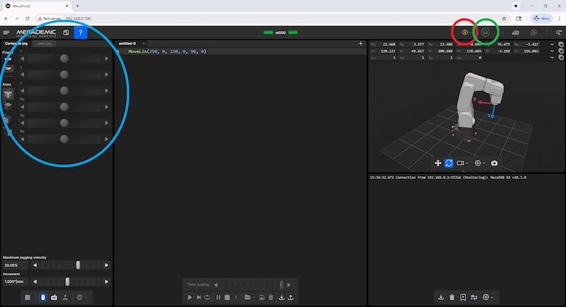
Figure 3. MecaPortal web interface. The red circle switches connection operating modes, the green circle activates the robot, and the blue section is the jogging interface.
The jogging can be done in joint, world, or tool coordinate systems, much like any other robot. In the web server interface, buttons on the far left side can toggle between the different jog modes, along with buttons and entry boxes for jogging or entering an absolute value. When in tool or world systems, you can jog the robot along a single plane, either xy, yx, or xz.
The various coordinate systems are Cartesian (x, y, z) systems, but there are subtle differences in function between each of them. The base reference frame (BRF) is static, fixed to the ground at the attachment point of the robot to its fixture. The world reference frame (WRF) is, by default, aligned with the BRF, but it can be moved to a point that aligns with external equipment to simplify the jogging and teaching process. Finally, the tool reference frame (TRF) is a point that aligns with the gripping location, so it must be set for each custom gripper. Fortunately, many grippers are predefined in the software, so the TRF is automatically applied when the tool is selected. The tool system uses the flange at J6 as its default reference point, so if you rotate the wrist, it will also rotate the x, y, and z directions of motion.
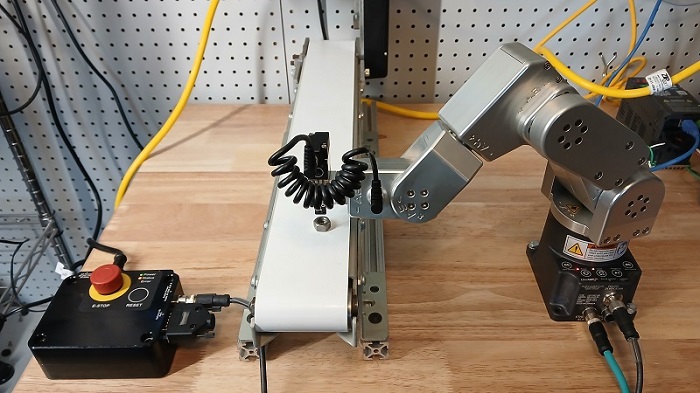
Figure 4. An example pick-and-place system with the Meca500 robot.
A Simpler Way to Robot
No robot can ever be a drop-in fit for every application. These robots are designed for small, high-precision applications. The simple setup and easy interface are beneficial for integrators, but the structured text coding can create some obstacles for PLC engineers. In the next article, we’ll have a look at writing simple scripts and controlling them from a PLC.
All images used courtesy of the author.