Facebook
 Google
 GitHub
 Linkedin
Tutorial: Setting up an Inovance HMI With A Mitsubishi PLC
This guide shows you how to create a simple Inovance HMI project and connect it to a Mitsubishi PLC using serial and Ethernet methods, including practical setup steps and common mistakes to avoid.
Human-machine interfaces, usually called HMIs, are essential for intuitive interaction between the operators and the automated system. It allows information to be displayed or for data to be input to the PLC without opening and editing the ladder logic directly.
The choice of HMI depends on many factors, including the nature of the project (environment, available space, etc.), compatibility with a range of controllers or mixed-vendor production lines, and certainly budget. The compatibility between the HMI and the controller is often the main factor in choosing an HMI.
In this article, we will look at how to connect an Inovance HMI to a Mitsubishi PLC using two common communication protocols.
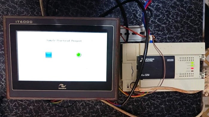
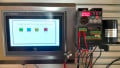
Figure 1. The setup features an FX3U Mitsubishi PLC and the Inovance IT6000 HMI showing a bit switch and a bit lamp.
System Architecture and Hardware Requirements
Before you start, you’ll need a Mitsubishi PLC (FX or iQ-F series) and an Inovance HMI. In this example project, we will use an FX3U PLC and an IT6000 HMI.
For software, Ino Touch Editor is used for the IT6000 series, or Ino TouchPad if you have the more modern revision, the IT7000.
To program the PLC, you’ll also need MELSOFT GX Works/Developer software. For review, please see this previous tutorial article.
Starting the HMI Project
Open InoTouch Editor and start a new HMI project by clicking ‘File’-> ‘New Project’. In the ‘Create a Project’ window, set the project name, choose the HMI model, and select the communication preference. For this example, we’ll set the screen to horizontal and pick our exact IT6070E (800x480) model. You can find the model number on the back of the HMI panel.
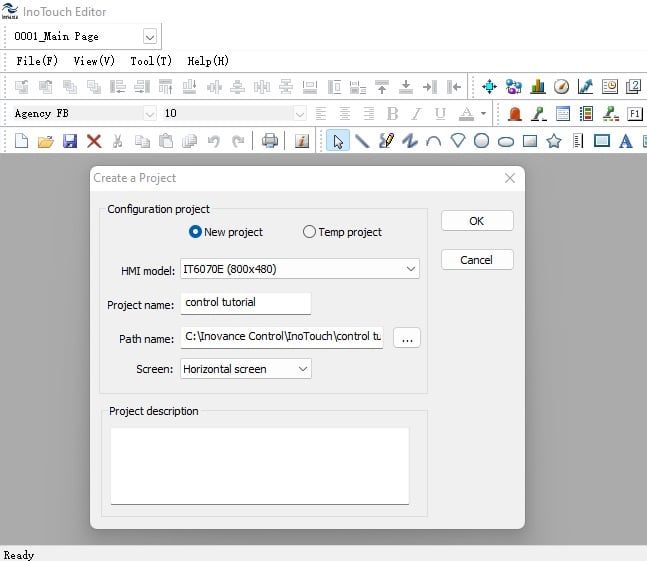
Figure 2. The new project setup window featured in the InoTouch Editor software.
After finishing the setup in Figure 2, click OK. A new window will appear to set up the device, which is the controller paired with the HMI.
Setting up Serial PLC Communication
Inovance HMIs work with many PLC models. Click the dropdown under ‘Producer Name’ and choose Mitsubishi. Then, select the device name for your specific controller model.
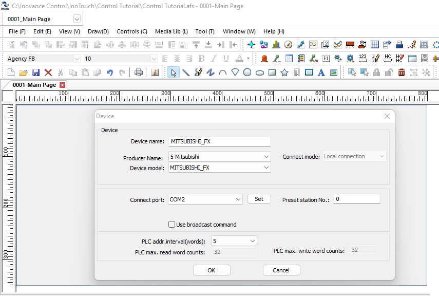
Figure 3. Selection of COM2 for RS-232 configuration.
After choosing the right device, pick the communication port that matches your controller.
The IT6070E has two DB9 ports: COM1 for RS-422/485 and COM2 for RS-232. For this project, we will use COM2 (RS-232) via a DB9 <-> MD8 cable for the connection. The Mini DIN 8-pin DB9 uses signal conversion to connect RS-232 (single-ended) to the PLC’s MD8 port, which uses an RS-422 for less noise.
In the device setup, select COM2 for RS-232. You can adjust settings like baud rate, parity, and data bits by clicking ‘Set’, but the default settings usually work well.
NOTE: This is not the communication for PC programming, so do not use the COM port assigned to your USB connection in your PC’s Device Manager.
Setting Up Ethernet Connection
Ethernet configuration in the IT6000 series depends on the HMI model and can be identified with the letter ‘E’ in the model number, like our IT6070E. The models ending with ‘T’ only support serial communication.
InoTouch Editor has built-in drivers for Mitsubishi PLCs. The FX3U PLC needs a separate Ethernet module because it does not have an Ethernet port. The FX5U has built-in Ethernet, so you do not need an extra module. When connecting the Inovance IT6000 HMI to a Mitsubishi FX5U PLC, Modbus TCP is the best supported communication method. Although Mitsubishi PLCs support SLMP (MC protocol), the IT6000 and InoTouch Editor mainly use Modbus for Ethernet and serial communication, so Modbus TCP is the most reliable choice in a mixed vendor setup.
Currently, InoTouch Editor does not support an FX5U-compatible SLMP driver. Because of this, you cannot use Mitsubishi’s native SLMP protocol unless you change the HMI model. However, the FX5U supports Modbus TCP when set up as a Modbus TCP server, and the IT6000 HMI can act as the Modbus TCP client. This setup lets the HMI regularly read and write PLC memory areas over Ethernet using standard Modbus function codes.
InoTouch Editor Modbus TCP Configuration
When using Modbus TCP, InoTouch Editor requires the Common Driver (ModbusTCP/IP). Unlike vendor-specific drivers, the Common Driver communicates using standardized Modbus objects, requiring explicit register mapping on the PLC side.
To set this up in the device configuration window, choose ‘2-Common Driver’ instead of Mitsubishi in the producer name dropdown, and select ModbusTCP/IP as the device model. Set the connection port to Ethernet and enter the PLC’s Ethernet IP address in the ‘PLC IP addr’ field, since the FX5U acts as a Modbus TCP server. Keep the port setting at 502, which is the default for Modbus.
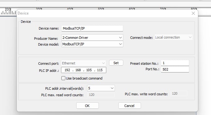
Figure 4. Device setup window for Modbus TCP, in which the HMI’s IP is assigned to 192.168.105.115.
Verify PLC IP Address
Over in GX Works 3, the FX5U should be configured with the same IP as the one assigned InoTouch, in this case 192.168.105.115, and the subnet mask as 255.255.255.0. This can be done by accessing the project’s navigation tree under the module parameter and clicking Ethernet port.
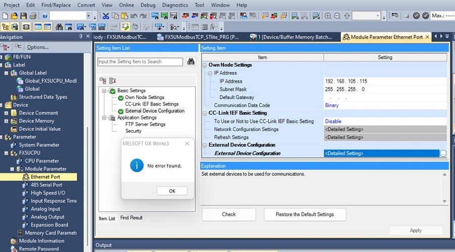
Figure 5. Image of GX Works 3 Module parameter setting for the PLC Ethernet port.
Adding Buttons and Bit Lamps
In the controls tab of the InoTouch Editor project, click on the switch to choose either a bit switch or a word switch. Move your cursor to the design area and place the switch where you want it. For this project, use a bit switch. After placing it, configure the control so it responds to the correct PLC address and works as needed. You can also change the switch’s design to fit your needs by double-clicking the bit switch, which opens the ‘Bit status transfer switch’ window.
In the ‘General’ tab of the window, set two key parameters to make the switch work. One is the read address, which sets the PLC control address. For this switch, we’ll use the M1 memory bit in the PLC.
Click 'Set' to open the device info settings, where you choose the PLC name, address type, and address.
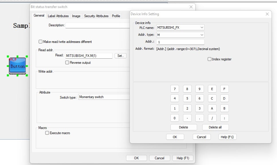
Figure 6. Device info setting window showing the PLC name as MITSUBISHI_FX, address type as M, and address as 1.
After assigning a PLC address to the switch, set whether it will be a transfer (selector) or a momentary switch. To change the appearance, click the Image tab, then select the library to see the available pre-designed button and lamp designs that fit your project. You can also upload your own images in Bitmap format for the bit switch or lamp.
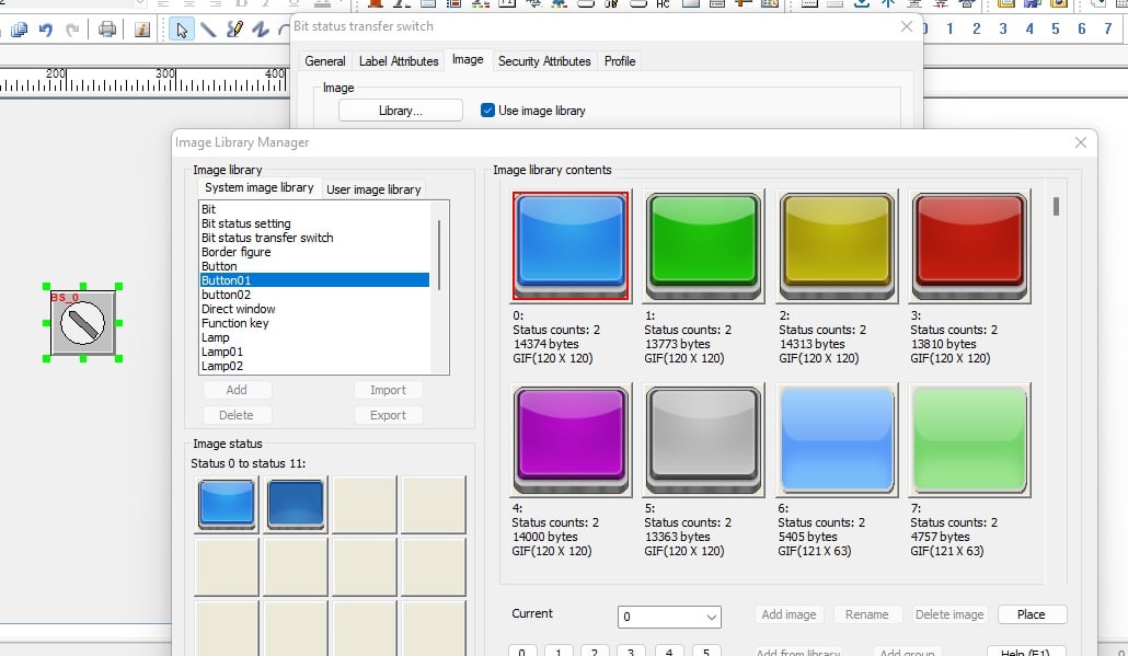
Figure 7. Image library selection for buttons and lamps.
Next, add a bit lamp to the design area from the control tab. After adding it, set the PLC output address for the lamp to M0, and change its image and color to fit your design.
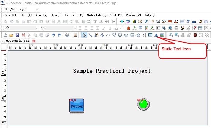
Figure 8. The 'Download' window configuration.
You can also add and format text labels for the individual objects, or for the screen itself.
Download and Functionality Test
When you are satisfied with the look and feel of the view area, click Tool -> Download to load the design to the HMI panel. This opens the 'Download' window, where you can use either a USB or Ethernet connection.
With the HMI and PLC connected by RS-232, you can now test the sample code. In this project, the PLC is connected to a physical green lamp as its output. The PLC receives input from the button on the HMI. The lamp shown on the HMI should respond at the same time as the physical lamp. The PLC ladder logic is set so that pressing the button once turns the green light on and pressing it again turns the lamp off. The logic uses a counter system to work as a single ON/OFF switch
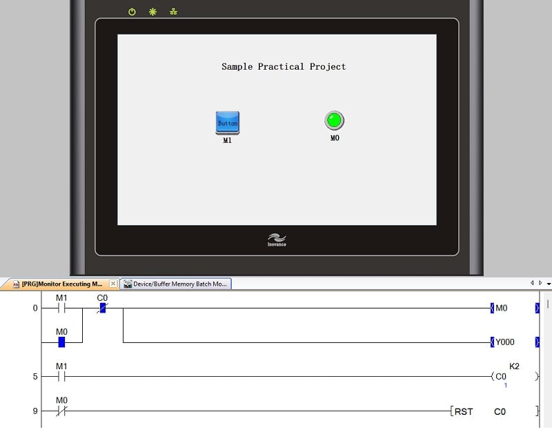
Figure 9. The working setup of the HMI design with the ladder logic in the PLC: When the HMI button (M1) is pressed, M0 and Y0 are latched and the counter counts to 1.
Building Interoperability Between HMI and PLC
This tutorial gives you the basics for setting up an Inovance HMI control system. These steps are not limited to Inovance HMI or the FX series controller; other brands use similar communication protocols and can work with mixed vendor platforms.
As control systems advance, efficient communication is essential for strong human-machine interaction. It is essential to keep exploring different platforms to best discover what suits your needs the most.
All images used courtesy of the author