Facebook
 Google
 GitHub
 Linkedin
Tutorial: Mitsubishi FX PLC With VFD and HMI Controls
In this article, we will learn how to set up a Mitsubishi FX PLC to drive a FR-D700 3-phase VFD, including detailed parameter settings, wiring, and HMI integration.
In many industrial setups, variable frequency drives (VFDs) are used to vary the rotation speed and direction of three-phase motors, allowing softer starts and stops. All VFD manufacturers offer models with different current, voltage, and horsepower ratings to suit custom motor control needs, most of which provide very similar control approaches.
I have implemented a sample project for this tutorial using Mitsubishi's FR-D700 VFD, adding a PLC and an HMI.
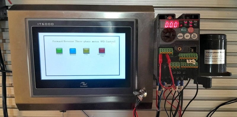
Figure 1. An HMI-controlled VFD setup for forward/reverse control of a three-phase motor.
VFD: Power and Control Circuit Wiring
Virtually all VFDs come with terminal headers that are labeled for easy identification and connection.
Power Connections
In the FR-D700 series, the power terminals are labeled R/L1 and S/L2 for a single-phase powered VFD, similar to the one featured in Figure 1. The two terminals allow for a live and a neutral connection directly from the circuit breaker. A separate, clearly labeled earth terminal is available. When earthing the VFD, it is often advisable to avoid common grounding with other equipment in the system. When connecting the three-phase motor on the output, the U, V, and W terminals are clearly labeled to supply each of the motor phases, plus the earth terminal.
Control Connections
When setting up the control circuit, it is essential to have a basic understanding of the location and purpose of each wire before getting started. The most commonly used input terminals are the STF (Start Forward) and the STR (Start Reverse), which control the forward and reverse motor directions, respectively.
A jumper is used to select between sourcing or sinking configurations, which, in this case, refers to the type of devices that will be connected to the inputs. If in sourcing mode, the PC (common +V terminal) must be connected via a switch to either the STF or the STR terminal for directional control. Or, if in sinking mode, the SD (common GND terminal) must be connected to the STF/STR terminals for directional control.
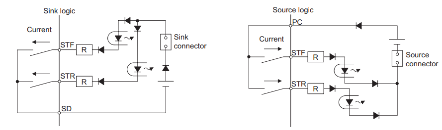
Figure 2. The circuits show the sink and source logic connection and current flow.
Ensuring the VFD's control input logic type matches the controller's output type is essential to maintain sink/source compatibility. Mismatching these types can lead to improper control signal operation or potential damage to the inputs.
Other essential terminals are the RH, RM, and RL, which allow for high, medium, and low speed control. To vary motor speed externally, a potentiometer can be connected across terminals 10, 2, and 5.
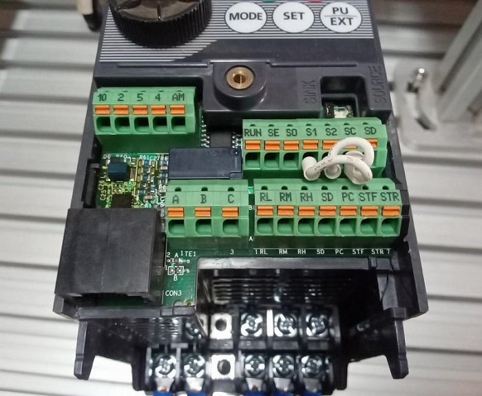
Figure 3. The VFD control push-in connectors have clear labels.
VFD Configuration and PLC Programming
When working with the FR-D700 VFD, some essential configurations should be done to suit different operational needs. When the VFD is powered on, text is visible on a small 7-segment LED monitor display along with a few keys labeled RUN, STOP/RESET, MODE, SET, and PU/EXT. The drive also features a circular knob and LED indicators to indicate the motor RUN status and the drives PU status. The PU mode is used to run and stop the motor locally using the mentioned keypad, and to ensure the maneuverability between the operation modes of the VFD. We will look at some essential settings.
The settings in the FR-D700 VFD are divided among various parameter numbers denoted by (Pr.), with the corresponding number of the specific setting. There are hundreds of parameters, but we will only investigate those required for this project.
The MODE key is pressed once to change a parameter, and the parameters are displayed on the LED monitor. Using the knob, the desired parameter number is then found and selected by pressing SET key. This shows a numeral display, and the value depends on the parameter you are setting.
We can adjust the value by rotating the knob once again and SET pressed twice to implement the change made to the parameter.
The most commonly used parameters include frequency, acceleration, deceleration, and control mode selection. However, more parameters can be adjusted depending on the motor control needs available in the VFD documentation.
In the table below, ‘PU’ (parameter unit) refers to the built-in keypad and potentiometer on the front of the VFD.
Table 1. Common VFD parameter settings are implemented for this example setup project.
| Parameter Name | # | Description | Settings applied for this project |
| Frequency Settings (in Hz) | 1 | Maximum Frequency | 120 |
| 2 | Minimum Frequency | 0 | |
| 3 | Base Frequency | 50 | |
| Acceleration and Deceleration Settings (in sec) | 7 | Acceleration time | 5.0 |
| 8 | Deceleration time | 5.0 | |
| Control Mode Selection | 79 | Operation mode | 1: PU for STR/STR and Frequency Control |
| 2: External STF/STR and Frequency Control | |||
| 3: External STF/STR and PU Frequency Control |
It should be noted that the base frequency is set based on the rating of the specific motor used. For my motor, the rated frequency is 50 Hz; the default value is 60 Hz. Only when Pr. 79 operation mode is set to 0 (PU Mode) can the frequency settings (Pr. 1, Pr. 2, and Pr. 3) be configured.
When Pr. 79 is set to 1, the motor rotation can only be started using the RUN keypad and the knob used for frequency control. For mode 2, STF and STR need an external switching method like a simple switch or a PLC, and the speed is controlled via an external potentiometer. However, for this project, operational mode 3 allows external start/stop commands, but allows us to adjust the frequency with the keypad potentiometer.
When integrating with PLC controls, we can change the operational mode to 3 to allow digital-only external control.
PLC Integration
For this tutorial, I have used the Mitsubishi FX series PLC (intro article here, in case you are new to MELSEC PLCs). However, any PLC brand can work just fine since we are using 24 V digital signals. I have connected the SD terminal of the VFD to the COM 1 terminal of the PLC since I am using the sink logic configuration.
STF and STR terminals are connected to the Y000 and Y001 PLC output terminals. For input connections, the contacts are implemented by momentary switches for forward (X001), reverse (X002), stop (X003), and an emergency stop button (X000).
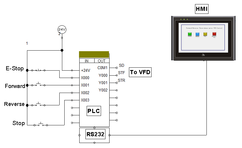
Figure 4. Schematic showing the PLC address and HMI implementation.
When the 'forward' push button is pressed, the output relay Y000 is activated to complete the contact with the SD connected to COM 1. The reverse push button, on the other hand, activates output relay Y001 to send a reverse signal to the VFD. Both stop and E-Stop buttons can cancel the motor rotation by deactivating both outputs, as shown in the ladder logic program in Figure 5 below. An HMI can be added to the system for improved control, as shown in the schematic.
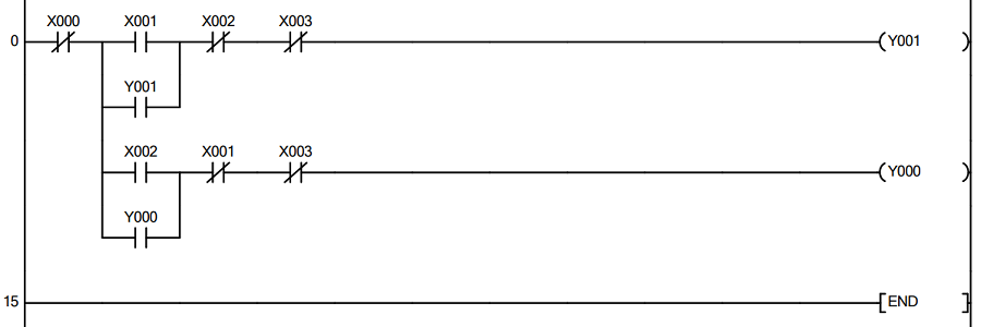
Figure 5. Ladder logic program for forward/reverse motor control that runs one instance at a time.
HMI Control
For this project, I used the Inovance IT6000 HMI panel to implement the forward/reverse control, assigning similar tags to the ones connected to the pushbuttons. The HMI is compatible with the FX-Series Mitsubishi PLC as it features an RS-232 communication protocol. When it comes to HMIs, there are no major incompatibility issues as most are built to work with a wide range of PLC brands. However, even as basic functionality remains the same, some variations with protocol support, ease of setup, and cost may influence selection.
Expanding the Project
If we wish to go further by adding an analog PLC module, we would adjust Pr. 79 to 2, adding flexibility in varying frequencies. However, if you are looking for a simple control, the setup in this article can be a great place to start. Additionally, the availability of documentation makes it easy to expand further to meet complex control needs.
Having learned how to set up Mitsubishi’s FR-D700 VFD, you can gain the confidence to explore with different hardware, noting similarities or differences in the control approach of three-phase motors.
All images used courtesy of the author.