Facebook
 Google
 GitHub
 Linkedin
Introduction to Mitsubishi PLC - FX Series and MELSOFT GX Developer
Mitsubishi's FX series PLC is one of MELSOFT GX Developer’s most popular automation solutions for small and medium-scale applications. Learn how to use GX Developer software to program the FX series PLC.
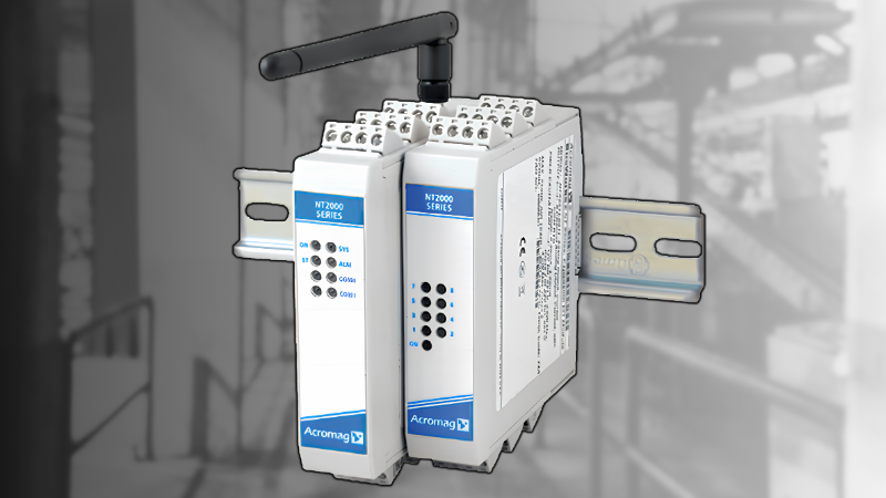
The FX series PLC is one of the introductory MELSEC product lines from Mitsubishi Electric. The company is widely recognized for the manufacturing of automation solutions across the globe. In this tutorial, we are going to guide you through the basic steps of using MELSOFT GX Developer version 8, which supports MELSEC controllers.
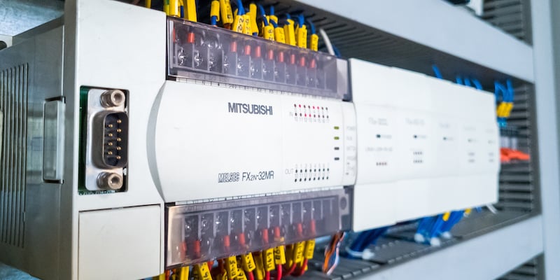
The FX series PLC, part of Mitsubishi Electric's MELSEC product line. Image used courtesy of Adobe Stock
Mitsubishi GX Developer Software
To start this tutorial, you will need to have the GX Developer software installed on your programming computer. With the latest version of the software (version 8) installed, we can get started with understanding the basics of how it works. Begin by launching the software on your PC.
Starting a Project in GX Developer
After opening the GX developer software, click on ‘Project’ in the far-left corner and then on ‘New project’. You can also use the shortcut Ctrl+N to create a new project.

Figure 1. Creating a new project.
After clicking on the new project, a pop-up window will appear in which specific parameters of the PLC should be fed before proceeding. Such parameters include ‘PLC series’, ‘PLC type’, ‘Project name’, and ‘Program type’. To select the PLC series and type, click on the drop-down arrow, which will bring out a listing to select from. In our case, we are using FXCPU as our series and FX3UC as our PLC type. For our program type, we can check the box that has the ladder text written beside it. Once you are done setting up these parameters, you can click okay to create the project.
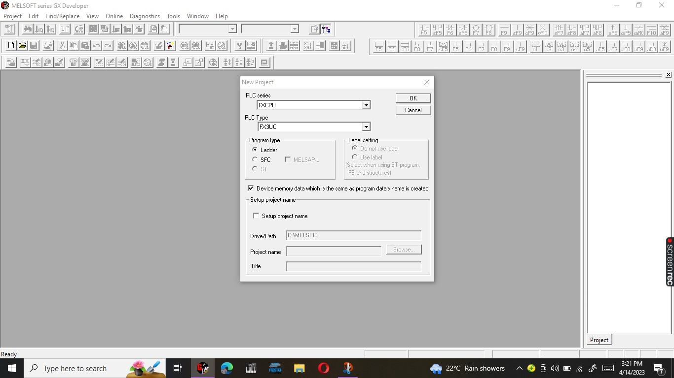
Figure 2. New project setup: ‘PLC series’, ‘PLC type’, ‘Program type’, and ‘Setup project name’.
Connecting to the Mitsubishi FX3U
To program the FX3U PLC, we need to establish a connection between GX Developer and the PLC. To do this, we must first connect our USB-SC09-FX programming cable between the PC and the PLC. After connecting the hardware, we can then establish the software connections. A COM serial port in the computer's device manager is used to determine the port on which the programming cable is connected—this is necessary for the transfer setup. In our case, the serial port is COM 4.

Figure 3. Identifying the COM port in which the USB-SC09-FX programming cable is connected from the PC’s device manager.
After determining the COM port from the device manager, click on ‘Online’ in the top ribbon of the GX Developer software and then ‘Transfer setup’ to select the serial port.

Figure 4. Click on “Online” then “Transfer setup” to open the serial port connection setup window.
After doing this, a popup window appears where our serial port acquired from the device manager can be selected.

Figure 5. Selecting the COM port.
Writing and Reading a Project from the FX3U PLC
With the transfer set-up correctly set, we can now select the read from PLC option to upload a program from the PLC. The read from PLC option allows you to access the program already loaded in the PLC. We use the write-to PLC option to download a new program to the PLC. When read from PLC is clicked, a similar pop-up window will appear as that of write-to PLC. Once the main PLC parameter and device data are checked, we can go ahead and click on execute.

Figure 6. Reading a program from PLC with the ‘Program MAIN’, ‘PLC parameter’, and ‘Device data’ checked.
Writing a Basic Ladder Diagram in GX
With the previous steps complete, the actual construction of a ladder program is simple. In the program tree of the project tree positioned in the right-hand corner, you can access the ‘MAIN’ program block where the ladder logic steps are stored.

Figure 7. The program MAIN in the project tree.
The N.O. contact and the output coil can be accessed from the toolbar above the workspace. To add them to the rung of the ladder, you simply select a position on the END rung and click the desired rung input or output from the toolbar. The referencing of the inbuilt I/O terminals is done using the syntax Xxxx for the inputs and Yxxx to represent the output. The addressing system, however, is dependent on the PLC specifications. For example, an FX-3U-32M means that the PLC has 16 input terminals and 16 output terminals, totaling 32 I/O terminals. With the ladder diagram ready, we can now convert it.

Figure 8. N.O. contacts X000 and an output coil Y000 in a ladder diagram.
Once the converted ladder logic program is ready, we can write it to the PLC. This will be fast since we have already established a connection using the COM port.
Programming the FX PLC
If you are new to the Mitsubishi platform, programming may be challenging at first. However, follow this simple, easy-to-follow tutorial to get started—the quickest way to learn something is to simply jump straight to it and design cool projects!