Facebook
 Google
 GitHub
 Linkedin
How to Use Mitsubishi’s GX Simulator and MX OPC Server in Factory I/O
Learn how to configure a MELSEC PLC using the MX OPC server and GX Simulator to connect to Factory I/O.
Factory I/O is a virtual 3D simulation and education tool, supporting a wide range of PLC drivers that students and professionals can use in learning. These drivers support major PLC brands, including Siemens and Allen-Bradley.
However, when it comes to Mitsubishi PLCs, Factory I/O lacks a native MELSEC driver, posing a challenge for students and instructors working in Mitsubishi-based environments. This is where the MX OPC Server acts as a workaround to this challenge, providing a gateway between GX Simulator and Factory I/O.
In this article, we will explore how to configure the OPC client driver to work with Mitsubishi's FX series PLC in a practical approach. Before we begin, please note that there are some prerequisites and tools required for easy follow-through. These aspects (covered in our previous article) include the Factory I/O software, Mitsubishi GX Works2/3, GX Simulator, and the MX OPC Configurator. Another aspect to note is that you may need some basic understanding of ladder logic.
Creating the PLC Logic in GX Works2
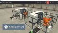
For this guide, we will consider an example scenario of a simple conveyor system that transports items from point A to point B within the system and uses a sensor to count the items. The scene features an emitter, one of the Factory I/O components that emits the process items (the boxes), and a remover component that receives and removes the boxes, as shown in Figure 1. We could think of these like the infeed and outfeed sections of a modular conveyor.
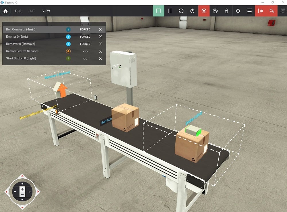
Figure 1. Conveyor system with sensor, emitter, and remover components in a virtual 3D factory environment.
To implement the logic, we will use GX Works2. If you are new to Mitsubishi PLCs, you can check out the foundational tutorial to get started. To describe the PLC connection addresses, we will consider the I/O mapping featured in Table 1 below.
Table 1. I/O table mapping of the practical example featured in Figure 2.
|
|
Description | Address |
| Inputs | Start Button (Light) | X000 |
| Retroreflective Sensor | X001 | |
| Outputs | Belt Conveyor (4m) | Y000 |
| Emitter (Emit) | Y001 | |
| Remover (Remove) | Y002 |
Launch GX Works2 and create a new project, selecting the PLC series that matches your control needs. For this example, we are using the FX Series PLC type.
Once created, add the first line of logic to activate the conveyor (line 0) and the emitter (line 4) using latching. Use a normally closed instance of the counter in series to deactivate the conveyor after three counts of boxes.
To activate the remover component, we will use the "always ON" contact M8000 (line 6).
To provide the counting action (line 8), the sensor sends a pulse to trigger the count whenever a box passes by. K3 denotes the count value, and C0 represents the counter device number.
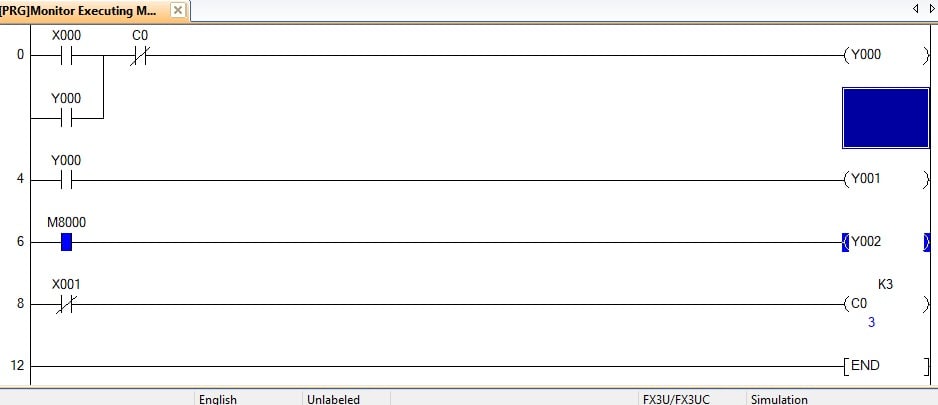
Figure 2. Ladder logic implementation for the sample scene.
Configuring MX OPC Server
This is accomplished by first launching the MX OPC Configurator and creating a new device, in my case, Dev01, which uses an I/O driver to communicate with the PC.
Click on 'Edit' in the toolbar and then add a new MX device. This opens a device property window, where you can keep or change the device name. In this same window, the primary device can be configured to GX Simulator2 by clicking on 'Configuration' to open the MX transfer setup popup window. In this new window, click 'Configure' to open the MX transfer setup wizard on the PC side. Use the dropdown and navigate to 'GX Simulator 2' in the PC side I/F setting. If one simulator is active, you can retain the target simulator setting as 'none' and the CPU series as 'FXCPU' or the PLC series you chose for the project. Once the settings are complete, click 'Next' and then 'Finish'.
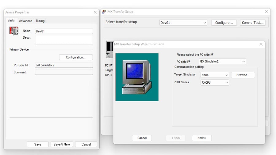
Figure 3. Device properties, MX transfer setup, and MX transfer setup wizard pop-up windows.
Configure Factory I/O for OPC DA Communication
Once MX Configurator is set up and the logic is implemented, the created scene is now ready for communication.
Back in Factory I/O, click on 'File,' then navigate to drivers to open the driver window, and using the top dropdown, select the OPC client UA/DA driver. In this case, the server has not been defined yet, meaning communication has not been established between the MX OPC server and the Factory I/O driver, as indicated by the red circular symbol.
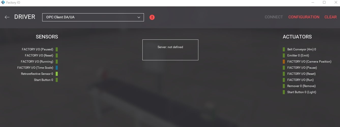
Figure 4. Selecting the OPC client DA/UA driver and MX OPC server configuration.
Click on ‘Configuration’ to browse for servers and select from the dropdown, and once selected, browse for nodes to update the I/O from MX OPC to the Factory I/O driver.
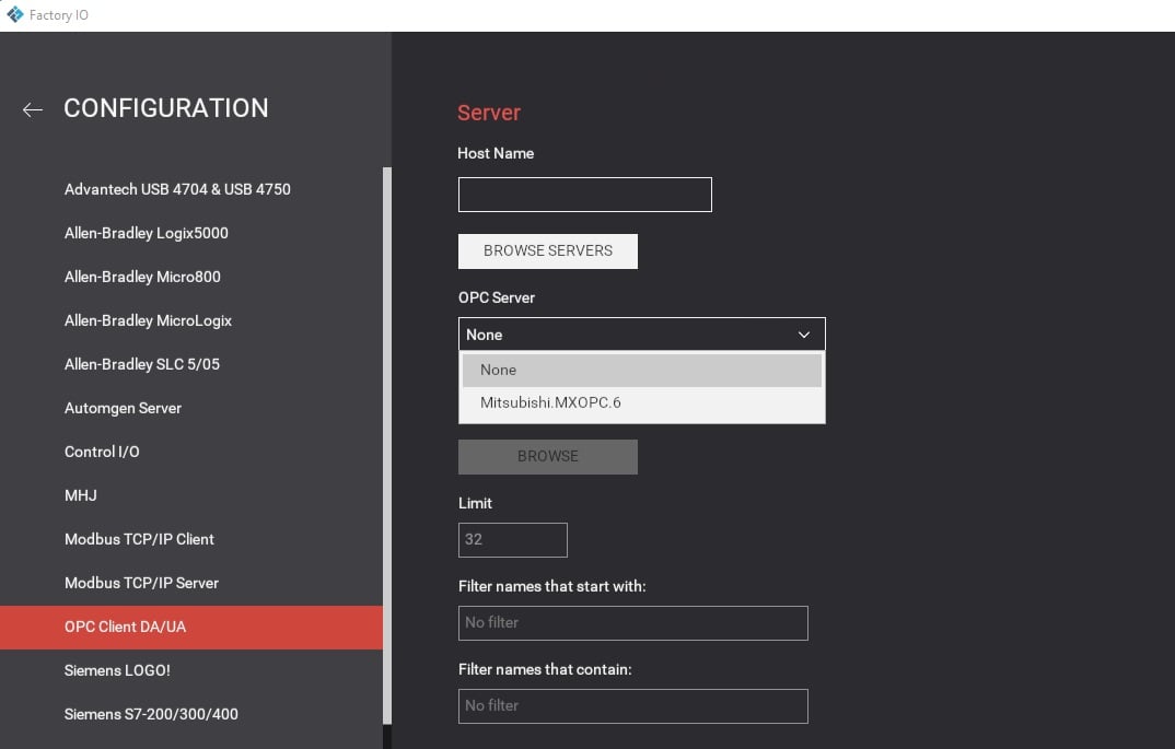
Figure 5. OPC server configuration by browsing for available servers and nodes to update the I/O tags as featured in the MX device settings.
Once this is done, the red icon turns to a green tick icon, and the connection points are visible to the driver.
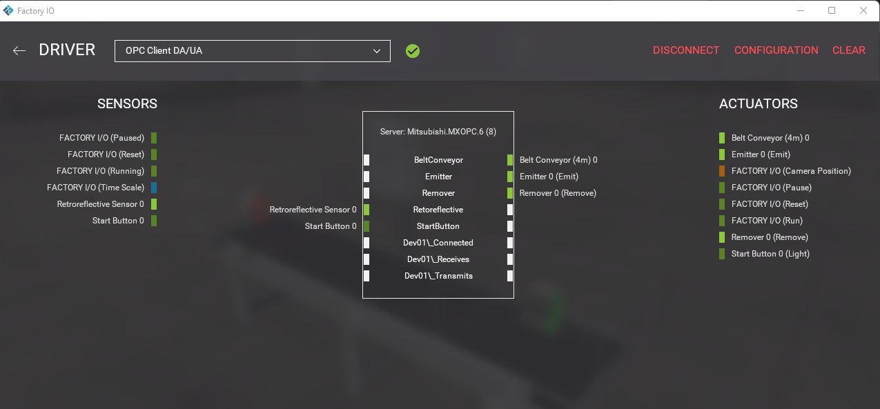
Figure 6. Drag the I/O to the available connection point on the connected server.
With the server configured and the I/O connection points established, run the complete simulation by clicking the start button on the standing control cabinet and observe: the conveyor starts with the emitter creating each box. Then, once the number of boxes hits three, the conveyor stops.
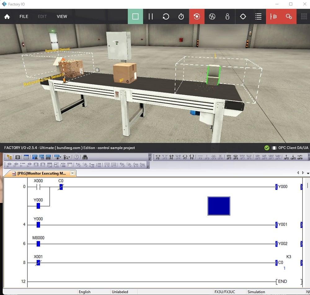
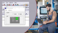
Figure 7. Final simulation Factory I/O and ladder logic real-time screenshot showing the sensor trigger count at 1.
It is worth noting that a common mistake encountered when working with configuration or I/O mapping is mismatched names, which can lead to problems in the outcome.
Another common mistake is the OPC server not being detected by Factory I/O after browsing, which is often due to a firewall blockage in most cases. It is, therefore, essential to ensure that both Factory I/O and MX Configurator run under the computer's elevated administrative privileges.
With this tutorial, you now have the basics to get you started. You can create custom scenes like the one featured in this article or try programming the prebuilt scenes in Factory I/O.
Stay tuned for future automation tutorials, and happy programming!