 Facebook
 Google
 GitHub
 Linkedin
Troubleshooting TRIAC Outputs For PLC AC Modules
When troubleshooting AC outputs driven by TRIACs, some confusing meter readings can result from the solid state properties of a series circuit. In this article, learn proper troubleshooting techniques.
In most discrete PLC systems, the process of troubleshooting output devices is quite simple. If the output terminal is working, then you should measure 0 volts when ‘OFF’ and the full source voltage when ‘ON’. For digital and relay outputs, this is true. It should also be true for AC outputs driven by TRIACs, but in these cases, some confusing meter readings can result.
A voltmeter is by far the most useful tool for the electrical troubleshooting technician. A quick reading with a meter can distinguish between open and closed circuits and can help to identify trouble spots — often with just one or two readings. One of the best parts about industrial control circuits is that the voltage readings will usually be either 0 volts, or the full source voltage (usually 24 VDC, or 120 VAC for control circuits).
Very rarely does the voltmeter show a partial drop in voltage, although it does happen sometimes. One of these rare cases is when troubleshooting AC output devices, like contactor coils or solenoids. If one of these 120 VAC outputs is connected to a relay output on a PLC module, a closed relay contact should send 120 volts, and an open contact should send 0 volts. Therefore, the troubleshooter should read those same voltages across the output device, providing evidence as to whether the problem is in the device, or the wiring, or the PLC itself.
When those coil devices are connected to a TRIAC AC output (sometimes simply called an ‘AC Output’), the readings across a bad coil may show intermediate values in the range of between 100 and less than 120 volts - a range that doesn’t seem logical.
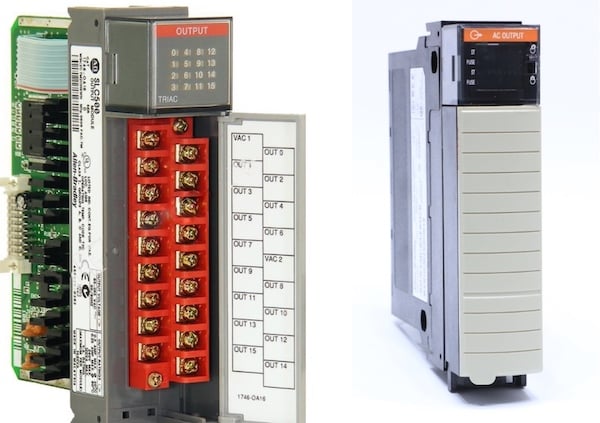
Figure 1. A couple of examples of PLC-based AC output modules with TRIACS driving the output current.
A gut reaction might say that if the PLC output is providing too little voltage, it is faulty and must be replaced. But beware! As we will see, this reading may in fact indicate an open wire inside a failed output device, and the TRIAC itself might be just fine.
What is a TRIAC?
The term refers to a solid-state device called a Triode for AC, or TRIAC. This is a silicon-based switch that is activated by a small control voltage from the PLC. In a sense, it’s just like a transistor (like a MOSFET) that is useful for AC loads. It does have a small amount of voltage drop when active, so the current levels are usually a bit more limited than for a relay circuit. However, because of the lack of moving parts, they have a nearly infinite switching life as long as used well under the maximum current rating.
As with all solid-state devices, the TRIAC never turns entirely ‘on’ or ‘off’. The resistance simply switches between extremely low to supply current to the output device, or extremely high to throttle the current flow to the output device. When the terminal is energized, it’s that very low, yet measurable resistance that leads to a tiny voltage drop and therefore, power dissipation and heat.
How to Test a TRIAC Output
To perform a simple multimeter test of a TRIAC AC output, place the AC voltmeter leads between the output terminal and the neutral (N) of the AC line.
Turn the output terminal to the ON condition. The voltage of the meter should read 24 or 120 vAC, depending on the system used.
Now turn the output terminal to the OFF condition. The voltage should now read somewhat more than half the supply. NOT 0 volts. It's hard to determine the exact expected value because not all TRIACS and not all meters have the same resistance.
But why does it read some intermediate voltage level? This is because of leakage current in solid-state devices.
The Leakage Current Problem
For most common TRIACs, the 'leakage current' refers to a manufacturer-guaranteed limit on the range of current which may be expected when the TRIAC is switched off. This quantity is extremely small, for example, the datasheet of the BT136, a 4A rated TRIAC, provides an off-state current quantity, this is the same as leakage current.

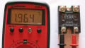
Figure 2. A BT136 TRIAC, the equivalent symbol, and the line from the datasheet specifying the off-state (leakage) current.
Off-State Resistance in a TRIAC
In this application example, the range is 0.1 mA to 0.5 mA with an applied voltage of 600 volts. A smaller applied voltage will naturally lead to smaller leakage currents. Calculating for the equivalent off-state resistance value would yield a range of 6 Megaohms to 1.2 Megaohms for those current values.
Keeping this value in mind, a technician is troubleshooting a device with an open coil and measures a voltage across the coil of 112 volts, expecting to see 0 volts. The PLC terminal is verified OFF, and yet there are still 112 volts. Has the output gone bad?
Representing The TRIAC as a Series Circuit
Since the coil is open, the multimeter completed the circuit the moment it was connected. That tiny amount of leakage current made its way through the meter, registering a voltage, but is this 112 volts a reasonable measurement?
A standard DMM has between 10M and 20M Ohms of internal resistance. Most good tools will be closer to the 20 Megaohm level. If the measured voltage is 112, and the internal resistance is 20 Megaohms, the current is around 5.6 microamps.
Turning back to the PLC, the TRIAC must be dropping the remaining 8 volts. Given the 5.6 microamps of leakage surrent, the equivalent resistance would be around 1.5 Megaohms. This fits within the scope of reasonability for that TRIAC, according to the spec sheet.
Most likely, the voltage value will be around 80-110 volts for a 120 VAC supply, and around 20-23 volts for a 24 VAC supply (smaller supply voltage = less leakage current and less voltage dropped by the meter).

Figure 3. Two circuits showing the actual output circuit with the open coil on the left, and the equivalent circuit with each component represented as a resistor on the right. Since the coil is open, this can be written as a simple series circuit.
What can Change the Voltage Drop?
A few factors will cause the measured voltage to be different.
First, the meter having a lower resistance will reduce the voltage measured (review the concept of a series circuit voltage divider).
If the output terminal is actually turned ON, the voltage will be 120 volts, even if the coil is bad. Be sure that the terminal is OFF before deciding the failure.
If the coil is functional, the resistance will be much lower than the meter, no more than a couple of hundred ohms. In this case, even the absolute max leakage current should be less than 0.5 mA according to the datasheet, so the voltage drop should be less than 0.25 volts for a 500-ohm coil. In the case of a good coil, the troubleshooting process follows closer to what might be expected for a relay output.
If that measurement value is a great concern, a resistor could be placed in parallel with the coil. If the value is around 10x higher than the coil (perhaps 5k to 10k ohms), then it will not greatly affect the current consumption of the circuit, but the resistance will still be much lower than the TRIAC itself so that the measured voltage of an open coil will be closer to 0 when the terminal is OFF.
Related Content


Many meters today have a function named LOW-Z voltage. it presents a very low impedance to the circuit and the output will read very near “0” Volts when output is off..