Facebook
 Google
 GitHub
 Linkedin
PLC Input and Output Module Troubleshooting Techniques
When inputs or outputs stop working, the equipment fails to respond and money starts slipping away. Dive into the concept of troubleshooting I/O without ever opening the PLC software.
The various peripheral cards and modules equipped with input and output terminals allow PLCs and controllers to interact with the physical world. Push buttons, switches, and sensors are examples of inputs to the PLC, with lights, relays, and contactors being among the more common PLC outputs.
I/O Device Failures
When these inputs or outputs are not working as expected, the equipment will not run, which could cost the factory a lot of money. Troubleshooting these devices does require some special tools and some technical skills. Within this article, I will cover both the technical skills and the various tools that will assist in the troubleshooting process.

Figure 1. Part presence using inductive metal sensing. Image used courtesy of Wikipedia
Input Modules and Memory Locations
Regardless of whether you have a card on a large PLC rack or if you are using remote modules, inputs to a PLC work in the same way. When the input terminal detects a change of state, the PLC memory bit changes from 0 to 1 or 1 to 0.
Within the PLC code, that memory location can be used to drive other sections of PLC logic. If you have an industry standard of 16 inputs per module, you will likely have 16 bits of memory, one bit for each input.
Output Modules and Digital Logic
When you want to drive a relay, turn on a light, or send a signal to a VFD, outputs from the PLC become very important. Output modules work in a similar fashion to the input modules, typically reserving one bit of memory for each output terminal on the module. When the memory bit is transitioned from 0 to 1, the output will energize.
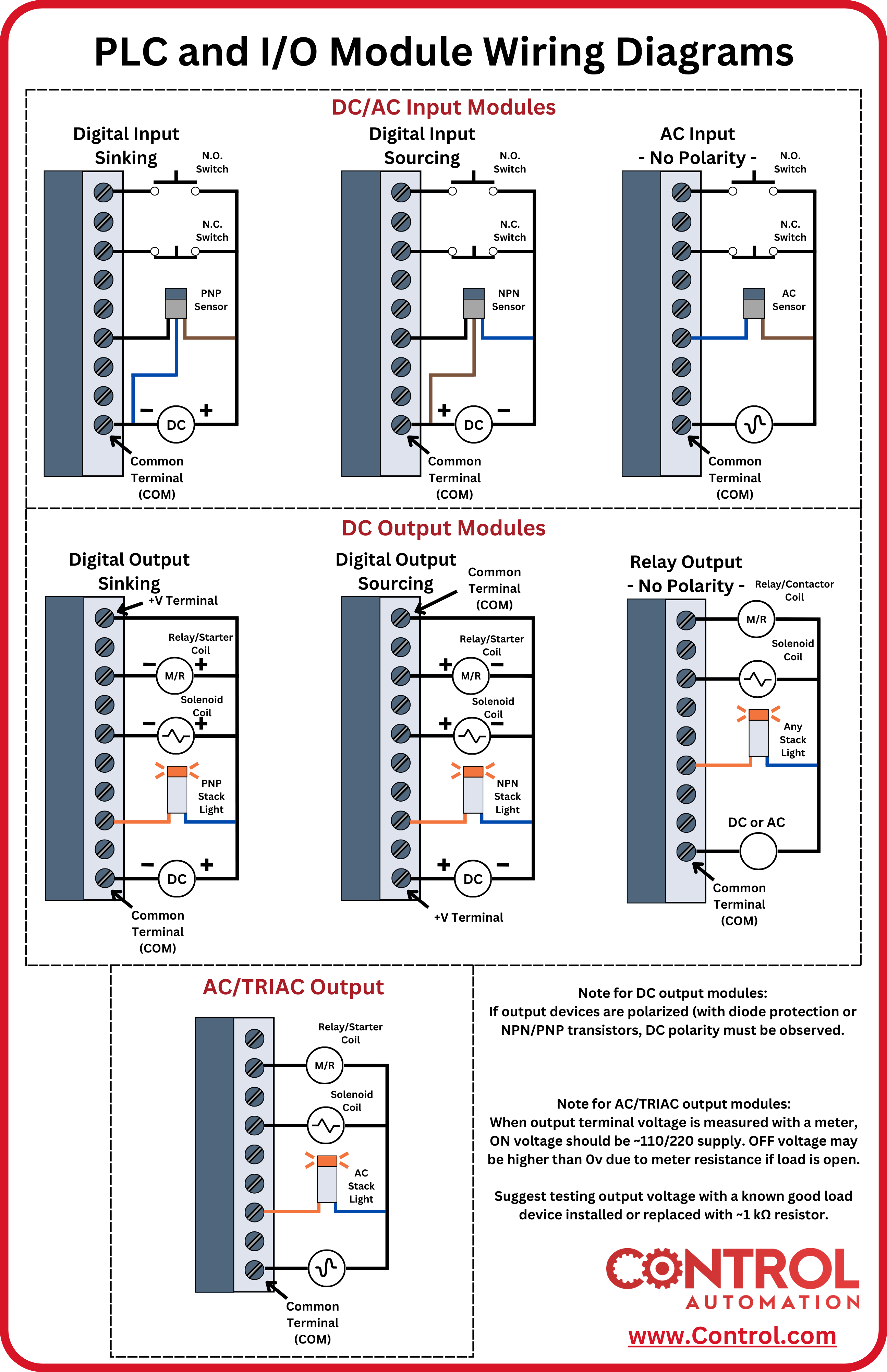
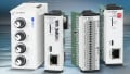
Figure 2. Illustrating the differences between various inputs, as well as output modules. Image used courtesy of Control Automation
Sinking Vs. Sourcing Modules
Both input modules and output modules can be sinking or sourcing, and it’s critically important to know if the module you are troubleshooting is sinking or sourcing. The terms sinking and sourcing dictate the direction of the current flow, and for further details, they are covered quite extensively in many articles.
If the output module provides voltage from each output terminal when that output is switched ‘on,’ that is considered sourcing (the most common output type).
The same logic applies to inputs but usually in the reverse direction. When voltage is provided to the input terminal when ‘on’ is detected, that is considered sinking (the most common input type).
You can usually tell if a module is sinking or sourcing by checking the polarity of the common connection. If the input module has a common ground (-V), you have a sinking module, but if the module has a common supply voltage terminal (+V), you have a sourcing module. Always consult the manual to make sure you know the type of module you are using, since many digital modules require a common connection to both voltage and ground, so first impressions may be deceiving.
Troubleshooting Input Terminals
Now that we understand how to determine the type of input module we are working with, let’s look at how we can troubleshoot why our input isn’t working.
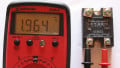
When dealing with a sinking input module, you must determine if there is actual, physical voltage at the input, and not simply rely on assumptions or LEDs dictated by the CPU logic. This can easily be done with a multimeter on the proper settings.

Figure 3. The proper wiring diagram for an input module. This module can be configured for either sourcing or sinking by reversing the power supply connections (bottom-left of the right-side image). Image used courtesy of Mitsubishi Electric (page 36)
- Configure your multimeter to read the correct voltage, either AC or DC, according to the electrical drawings.
- Place the positive probe in the terminal on the input module and the negative probe to ground
- Activate the input device (press the push button, close the relay, or flag the sensor)
- If using a sinking input, you should see voltage at the input terminal. If not, follow the same steps for each device in the upstream circuit until you find the device that is not completing the circuit (open).
- If using a sourcing input, switch the meter to the continuity test function, and you should hear a beep and see low resistance. If not, measure the voltage across each device in the downstream circuit until you find the device that is not completing the circuit (open).
If you are troubleshooting a push button or relay, the above steps will work fine, but if you need to troubleshoot a sensor, there is an additional step. You must ensure the sensor has enough voltage.
Most sensors (like proximity sensors, optical sensors, etc.) require a dedicated conductor at 24 VDC. If the voltage drops too much, you may not get an output signal strong enough to energize the input, but the indicator light may still be on.
Troubleshooting Output Terminals
Troubleshooting output modules is similar to inputs, although most outputs are sourcing. You need to reference any electrical drawings and manuals to understand what type of device you are working with, and the type of voltage the device uses. With a sourcing 24 VDC output module, you will want to check for 24 volts at the terminal, referenced to ground when the output is ‘on.’

Figure 4. The proper wiring diagram for a sourcing output module. Voltage may be measured directly at ‘Output Channel 0 (through 3).’ Image used courtesy of Rockwell Automation
Outputs can be forced on or temporary logic can be used to toggle on outputs for testing purposes. If your multimeter is showing 24 volts at the terminal when the output is on, then you will need to inspect further downstream to find where the circuit is not completing. Sensing voltage at the terminal but not at the device could happen because of a faulty connection at a sensor or terminal of a relay.
Never, ever connect an output terminal directly to ground or the negative DC supply as this creates a short circuit and internal damage could occur. You always need to have a resistive load between the output terminal and ground. In summary, the output module needs to see a completed circuit from the output terminal to the common terminal

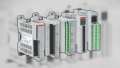
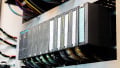
Figure 5. LEDs indicating the status of the CPU and a digital input module of a Siemens ET200SP remote I/O rack. Image used courtesy of Siemens
I/O Status Indicators
Most input and output modules today have LED indicators that display visually when the I/O terminals are energized. For the most part, you can trust these indicators, but there are occasions when the indicator light is on, yet the terminal or conductors have been damaged or are dysfunctional. For example, an output may display the LED when energized, but the terminal was not supplied with the proper common connection.
With older equipment, outputs can sometimes be damaged to the point where there is no voltage at the terminal when the output is on. The indicator will still light up with a false ‘on’ state. For this reason, always use a multimeter to verify if an output is on. Regardless of how easy it should be to troubleshoot I/O modules, it is critical to understand what voltage must be present (and when) in order to positively identify and trace faults and return your equipment to operational status.
Featured image used courtesy of Adobe Stock