 Facebook
 Google
 GitHub
 Linkedin
Process Noise Sources and How to Fix Them
Noise signal sources occur primarily from radiofrequency interference (RFI), often in the form of impulse functions or arcing. How do you mitigate process noise from your control system?
Wouldn’t it be great if all data acquisition devices only measured the signals of interest? In reality, sensors pick up voltage and current signals regardless of sources, desirable or undesirable. The desirable, real signal is often hidden by process noise sources, affecting measurements and wreaking havoc on process control loops.
Noise Signal Sources
There are several types of noise found in process control. We will cover RFI and aliasing, followed by mitigation techniques for both.
Radiofrequency Interference (RFI)
Because modern sensors generate either a voltage or current output, most noise sources are electrical. Radiofrequency interference (RFI) occurs when an undesirable signal is received and included in the data collection.
What are the actual sources of noise? Virtually anything with electrons flowing through it can generate noise. Consumer goods, such as microwave ovens and cell phone chargers, can generate a “hum” on the signal line.
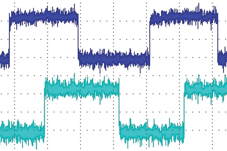
Figure 1. Two square waves affected by measurable noise. Image used courtesy of Encoder
These are typically at a narrow set of frequencies, so they can often be filtered out with a notch filter. And the same goes for motors running at a constant speed, fluorescent lights, or other such devices.
Another annoying source of RFI is impulse functions. The idealized impulse function is infinitely quick, and thus represents all frequencies evenly. In reality, this is not possible except for the brief duration of the pulse when there is a noise signal across virtually all frequencies.
Impulse signals arise anywhere there is arcing. Arcing occurs whenever contact is made or broken, such as when mechanical relays or switches operate. Suppose pressure is measured continuously. A mechanical relay closes to switch on a reserve pump. When the relay closes, an arc is briefly generated, showing up in the pressure data as a random spike.
Low Sampling Rate (Aliasing)
Besides RFI, the sampling rate can cause false signals as well. It’s not quite noise, but it still leads to problems. Choosing a sampling rate that is too low can lead to “aliasing,” where the signal is misrepresented.
Aliasing can be witnessed on the highway. At highway speeds, (safely) look at the next car’s wheels as they spin. If you watch, sometimes they will look like they are spinning backward or even holding still. This is because your eyes are “sampling” the wheel too slowly.
Representing this electrically, imagine a high-frequency signal sampled every so often. Little is known about the true signal between each sample, so the engineer (or the software) interpolates between the sampled points to recreate the waveform.
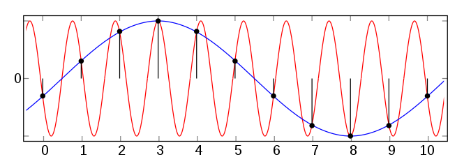
Figure 2. The red line is the true signal, and the black dots are the sampled data points. Image used courtesy of Moxfyre
As seen in figure 2, the blue line is the interpolated signal. Clearly, the frequency of the blue line does not accurately represent the real signal in red.
This can be a problem with hall effect sensors in flow meters, anemometers, or motor speed tachometers. Magnets on the shaft pass the sensor, causing a pulse train. The rotational speed is calculated from the pulse train’s frequency. The rotor may spin faster than the data represents if it is not sampled fast enough.
Noise Source Mitigation Techniques
Mitigating RFI: Cabling Techniques
RFI is the main source of process noise. To limit it, place all sensor wires away from other electrical devices. Moving sensor wires can help, but it is often hard to do. Bundled wires are convenient for installation and operation.
The next step is to ensure wires are as short as possible because longer wires mean a longer antenna. The longer antenna picks up more signals across a larger frequency range.
If neither of these is possible or does not reduce the signal noise, consider using a coaxial cable or a twisted pair. The coaxial cable has the signal line surrounded entirely by the coaxial cable’s braid, meaning signals are absorbed in the braid and grounded.
The measured signal travels through the signal wire from the sensor. Twisted pairs are not as good at reducing RFI as coaxial cable, but they tend to cancel some RFI.
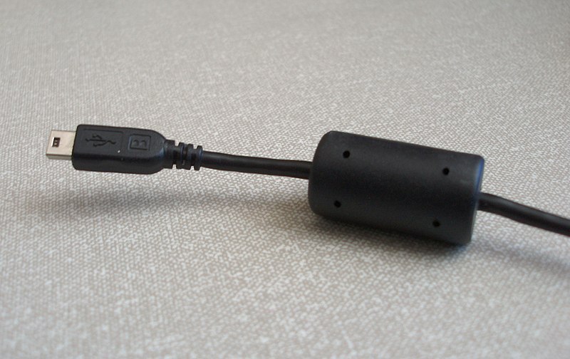
Figure 3. Ferrite bead on a USB cable. Image used courtesy of Stwalkerster
Another cabling technique is to wrap the cables through a ferrite bead, or choke. This technique is most advantageous for high-frequency signals. Ferrite beads are common on many consumer goods, such as laptop power supplies and computer peripherals.
Mitigating RFI: Wiring Techniques
Besides cabling, sensors can be wired in several ways to reduce RFI. Two common methods are “single-ended” and “differential mode.”
In a single-ended connection, a sensor requires one wire, perhaps powered and grounded at the sensor location instead of relying on the data acquisition system to provide them. The advantage is that only one channel is required for sensing in this manner, meaning a 16-channel device can record 16 signals.
However, this system has one single wire acting as an antenna. It also assumes the ground at the sensor and the data acquisition system are the same, which may not be true, contributing to a noise signal. Instead, differential mode connections can be used.
In differential mode connections, two channels are used for each sensor. Instead of comparing the signal wire to ground, the two signal wires are compared together so that the signal to interpret is the difference between the signal wires.
The advantage is that the two wires can be connected through a coaxial cable or twisted pair, and some of the RFI is lost. In theory, any signal interfering with one wire will interfere with the other, but in the opposite direction, canceling the noise. The disadvantage is that the same 16-channel device will only record eight signals.
To limit aliasing errors, the Nyquist Theorem states that the sampling frequency must be at least twice the maximum expected signal frequency. This means if a 100 Hz signal is expected, the sampling rate should be over 200 Hz. By doing so, the frequency will be accurately represented. If the entire waveform must be recreated, think in terms of 10 times the maximum expected signal frequency.
As the world becomes electrified with more signals, the challenge of preventing and removing unwanted signals will become even more important. How do you mitigate noise sources in your process control?


You forgot sample jitter. Sampling and uneven intervals will result in errors especially if the samples are to be digitally differentiated.