Facebook
 Google
 GitHub
 Linkedin
Developing Totalizer Function (Flow Totalizer) on a PLC
Converting from flow rate measurements into total flow over a period of time requires the use of a flow totalizer. Flow totalizing can be done with a standalone device or with a PLC mathematical algorithm.
Flow Totalizing
A flow totalizer will calculate the amount of fluid or gas passed by a flow sensor in a specific amount of time. Usually, the time period is considerable, as in a day, week, or month. Typically, these totalizers are separate devices with little to no outputs to other control systems.
An example of a flow totalizer would be a water meter in a typical home. The water company uses totalizers to know how much water has been consumed between readings. Standalone totalizers are great for easily accessible areas or when the data needs to be read by an operator.
Some totalizers will have relay outputs that can be configured for low-level or high-level alarms. If your control system needs access to the amount of product per unit of time, then a standalone totalizer may not be the correct device. Regardless, you can easily program your control system to function as a totalizer using simple sensors.
How to Measure Flow
Before we get into programming, we need to understand the different ways we can measure flow in a pipe. One of the most accurate ways is to use a flowmeter, but you can also use a flow totalizer or sensor.
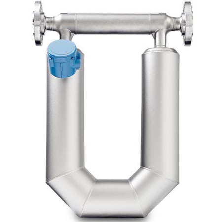
Figure 1. The Coriolis flowmeter requires space for a U-shaped section of pipe. Image used courtesy of Emerson
Flowmeter
A flow meter will measure the current flow of the product at that moment in time, usually in volume/time, with time in seconds or minutes. It reports this flow with an analog signal, typically 4-20mA or 0-10VDC. This signal will represent a minimum and maximum flow rate.
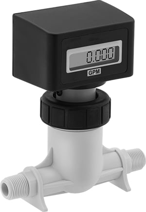
Figure 2. A washdown totalizer for water. Image used courtesy of McMaster-Carr
While this meter style is accurate, it is expensive and requires specific pipe layout requirements. For example, the Coriolis flowmeter requires space for a U-shaped section of pipe.
Flow Totalizer
As mentioned above, a flow totalizer connects to a flow sensor and reads the pulses to calculate the total flow in an hour, day, month, or running total. Typically, a totalizer is a standalone product that displays the amount of fluid that has passed by the sensor.
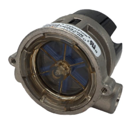
Figure 3. This rotor flow sensor features a VDC pulsed output. Image used courtesy of Gems Sensors [PDF]
By taking a reading each day and subtracting the difference, you can easily calculate the amount of product consumed each day. Or, some totalizers can be configured to reset after a specific amount of time.
Flow Sensor
A flow sensor is mounted inline of the flow and pulses a signal every time a specific amount of fluid has passed by it. A typical flow sensor will consist of a magnetized or magnetic paddlewheel.
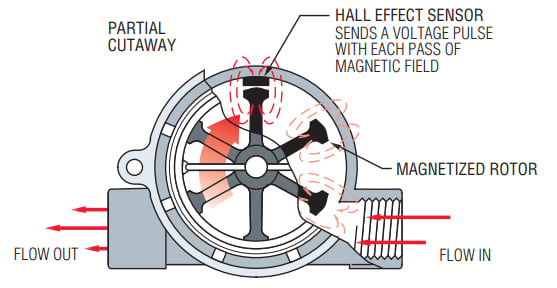
Figure 4. The operating principles of how a hall effect sensor is utilized in flow sensors. Image used courtesy of Gems Sensors [PDF]
As fluid pushes the wheel, the paddle is sensed, and the sensor sends out a pulse. These sensors will often have hall effect sensors to detect the magnetic field disruption as each paddle passes.
Signal From a Flow Sensor
The signal from a flow sensor can come in many forms, such as analog or pulses. If your sensor is analog, you will need to scale the incoming signal to figure out the flow per minute. Then, calculate how much time has passed at that flow rate to determine the total volume.
If your sensor uses a pulsed output, an extra calculation is required. A pulsed output will have a frequency; this frequency will change as the flow increases or decreases, but there should be a max frequency relating to the max flow.
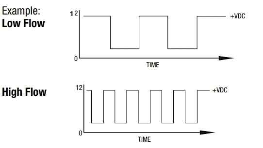
Figure 5. How frequency output signal looks in graph form. Image used courtesy of Gems Sensors [PDF; Note: the top graph fixed to 0–12 on the Y-axis]
You need to ensure that the sensor will not pulse the signal faster than the programmable logic controller (PLC) will scan the code. This is referred to as scan time.
Scan Time (Nyquist Theorem)
The scan time of a PLC is the amount of time it takes for the processor in the PLC to scan all of the code once. If inputs are toggling on and off faster than the PLC can scan the code, the input state will be missed and not processed. This is also known as the Nyquist theorem of frequency.
For example, you need to measure 100 pulses (Hz) in 1 s but your device can only measure 30 Hz/s. Per Nyquist, you should either change out or upgrade your device so it can sample at twice the frequency (e.g., 200 Hz/s).
So, if your frequency is too high, you may not process pulses sent from the flow sensor. If your sensor is already fixed and has a high frequency, you can always add a high-speed counter card. This is a special card that will scan an input and report the frequency of that input.
Developing the PLC Totalizer
Once you have selected a flow sensor with a frequency low enough for your program to catch every pulse, you now need to program a way to count the number of pulses in one second to determine the frequency. Upon knowing the frequency, you can calculate the flow rate using the formula provided by the flow sensor manufacturer. Or, if each pulse represents a specific volume, simply count the inputs and scale to the engineering units required.
Now that we’ve covered totalizer theory, let’s look at a real-life application.
Example of Developing the PLC Totalizer
I used an inexpensive flow sensor from Amazon to measure the amount of water entering a tank. The PLC was an Allen-Bradley Micro820 with no high-speed counter option installed and a scan time of 4 ms. The flow sensor was a DIGITEN FL-408 pulsed output with a max flow of 30 L/min.
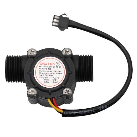
Figure 6. The flow sensor that I used from Amazon. Image used courtesy of DIGITEN
The flow sensor datasheet provides a formula of F=7.5*Q. This formula tells me at 30 L/min, I can expect a frequency of 225hZ. At 225hZ, I can expect a period (one cycle of the signal) to be 4.4 ms (1/225).
Instead of purchasing the high-speed counter option, I decided to try using the standard analog input. I connected the sensor output to the analog input and used a “greater than” function block to drive a counter. Anytime the input was greater than zero, I would increment the counter.
After one second, I would capture the counter value and calculate the flow in L/sec, so I have a new flow rate every second. I then use this flow rate to calculate the total volume for one second and add that to the previous volume.
Sadly, this didn’t work very well.
The flow rate fluctuates too much during the one-second calculation time, and I believe I’m missing some pulses. Despite the data not being 100% accurate, it works for a rough measurement of total volume. You can still use the total volume to make some minor decisions.
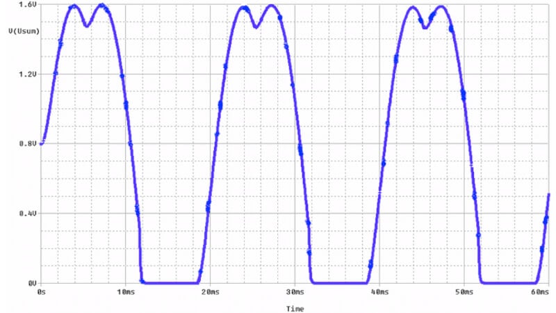
Figure 7. An example of what missed pulses look like on a plot chart. Image used courtesy of Borcosi et al.
If I had the high-speed counter card, I would have an accurate, up-to-date frequency, and would be able to calculate my flow rate faster. An accurate flow rate would give me a more accurate reading on my total volume collected.
The flow sensor I’m using also doesn’t support 24 VDC, so I used a 24 VDC to 5 VDC converter and the analog input to the PLC. If I used a 24 VDC sensor with a high-speed input, I’m sure I could get a more accurate flow rate measurement and total volume calculation.
When have you tried a cheaper device and found that it may not work as well as you’d hoped? What were your results?