Facebook
 Google
 GitHub
 Linkedin
Using Factory I/O With a Virtual Siemens S7-1200 PLC
Learn how to control the Factory I/O PLC system simulator using a virtual Siemens S7-1200 PLC, a great tool for testing, training, and automation development without hardware.
Getting access to physical PLC hardware is often difficult for educators, students, and engineers working remotely. Factory I/O’s virtual 3D environments let you use sensors and actuators to closely mimic real-world systems, working with common PLC brands both physically and virtually.
In this tutorial, you will connect a virtual Siemens S7-1200 PLC to the Factory I/O environment so you can create, control, and test logic without any physical hardware.
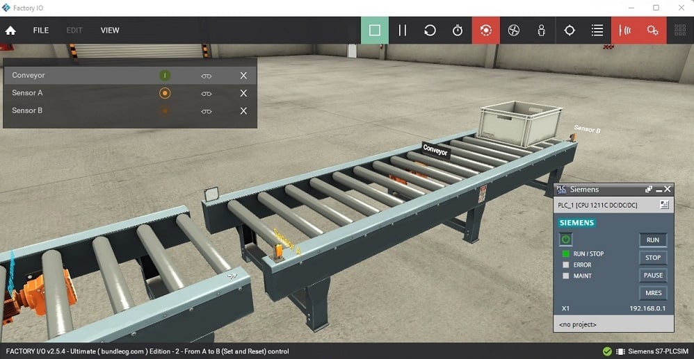
Figure 1. The Factory I/O scene for the tutorial.
Preparing the Virtual S7-1200 Environment
Before you start, make sure you have Factory I/O (Siemens or Ultimate edition, or a valid free trial), Siemens TIA Portal, and an S7-1200 PLC simulation environment that matches your TIA Portal version. In this tutorial, I am using version 17.
To set up the virtual PLC environment, download the S7-PLCSIM V13-17 Factory I/O template. Make sure it’s compatible with your TIA Portal version. After downloading it from the official site, open the project and update it to your current TIA Portal version. You can rename the project by clicking ‘Save as’. The template is already set up for Factory I/O and includes a function block called in the ‘Main OB1’ in Network 1. Do not delete this block.
In the project tree, click the controller and then the simulation icon to open PLCSIM. Next, in the ‘Extended download to device’ window, choose PN/IE in the ‘Type of the PG/PC Interface’ field. Below that, as shown in Figure 2, pick PLCSIM from the dropdown menu. After setting this up, click ‘Start search’, select your device, and click ‘Load’ to open the S7-PLCSIM window. Once it’s open, click Run Mode.
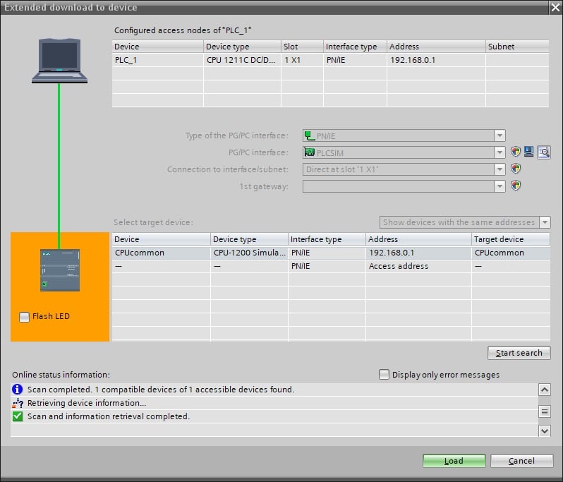
Figure 2. Simulation configuration window, after opening the project template.
Preparing the Factory I/O Scene
To set up the virtual 3D factory, open Factory I/O and go to the scenes section to pick a pre-made factory scene. For this project, I chose a simple “Point A to B conveyor system” with one sensor at the start and another at the end of the conveyor (shown in Figure 1). If you are new to Factory I/O, you can read our introductory article to help you get started.
After adding the scene, add the driver by clicking ‘File’ and then ‘Drivers’. In the dropdown menu, choose Siemens S7-PLCSIM instead of Siemens S7-1200/1500, which is used for physical PLC hardware. With the PLC simulation software open, click ‘CONFIGURE’ in the top right corner to open a new window. Set the CPU model to S7-1200, return to the driver selection window, and click ‘CONNECT’. A green tick icon will appear next to the driver to show the connection is successful.
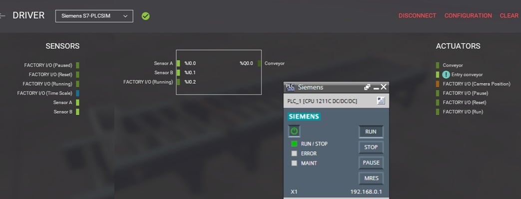
Figure 3. Successful connection of Factory I/O setup and S7-PLCSIM indicated by the green icon.
Once you are connected, map the I/O by dragging and attaching the input and output devices as shown in Figure 3. Next, add PLC tags in TIA Portal that match the ones in the Factory I/O driver. In the project tree, add a new data tag and assign names to the inputs as shown below. After mapping the I/O, you can set up basic control logic for the scene using start/stop latching logic.
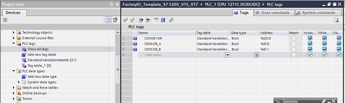
Figure 4. The PLC tags for the project are mapped in TIA Portal to match the ones assigned in the Factory I/O driver.
In the project tree, under program blocks, add a new function block and name it ‘START_BLOCK’. In the first network of the function block, set up the ladder so that when SENSOR A is triggered at the start of the conveyor, the conveyor output is latched. When SENSOR B is triggered, the latch is released, and the conveyor stops. After you finish the logic, call it (START_BLOCK) in the Main (OB1) in the second network and then compile. The choice of input as normally closed or open contact depends on the sensor’s signal when not activated. For instance, in this project, the retroreflective sensor gives a true signal unless the reflective path is blocked, making the use of its normally closed contact as a trigger practical, rather than normally open.
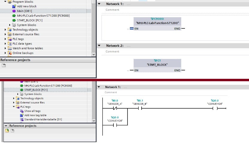
Figure 5. Main OB1 in the top image shows the default communication block and the START_BLOCK function. The START_BLOCK function block (bottom) shows the implemented ladder for the scene.
After you compile the program, download the logic to the virtual PLCSIM and switch it to RUN Mode. This way, the PLC program will respond in real-time as inputs change in the Factory I/O environment. To test your project, go back to Factory I/O and click the ‘Play’ icon. The conveyor should start and stop when the bin reaches the end.
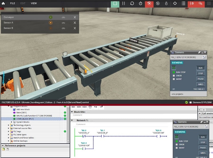
Figure 6. Real-time monitor response of PLC logic showing cancelled latch and the Factory I/O scene showing the bin at sensor B.
If your project does not work as expected, there may be some common issues causing the problem.
First, check for mismatched I/O addresses, look for input changes that do not match output actions, and verify that the PLC is in RUN mode. To find these issues, use diagnostic tools in TIA Portal to watch the state of tags as the logic runs. Factory I/O’s diagnostics, like a lighter green color when active and a dull green when off, can also help you check sensor activation and actuation commands. Using both tools helps you figure out if the problem is with the PLC logic or the simulation setup.
Performance Consideration in Virtual PLC Simulations
Even though using a virtual PLC removes hardware limits, performance is still important when working with Factory I/O and the Siemens S7-1200 PLC. It’s important to understand how simulation update rates, scan time, and program structure work together to build realistic and scalable automation logic. In a virtual setup, the PLC runs in a cyclic scan just like physical hardware. During each scan, the PLC reads inputs, runs the logic, and updates the output. Factory I/O updates the simulation at a set refresh rate, which can cause a delay in simulation changes if there are several PLC scans. If the PLC scan time is slow, the simulation may lag.
To get realistic results, the PLC scan time and Factory I/O update rate should be closely matched. If they are too different, you might see missed transitions or delayed actuator responses. For example, in this tutorial’s sample project, the bin could fall off the conveyor if there is a delayed response.
Eliminating Hardware Barrier in Siemens PLC Training
Using the virtual Siemens S7-1200 PLC with Factory I/O lets engineers and learners develop, test, and refine automation logic in a realistic environment before working with real machines. By removing the need for physical hardware, simulation-based projects help you learn faster, improve your logic, and get ready to implement real industrial systems.
If you want to explore Factory I/O further, with other PLC brands, like Mitsubishi PLCs, you can click here to get started. Stay tuned for more automation tutorials, and as always, happy programming!
All images used courtesy of the author