Facebook
 Google
 GitHub
 Linkedin
Measuring Flow Rate: An Introduction to Flow Gauges
For many manufacturing processes, it is extremely important to measure the exact rate at which fluid is moving or flowing. We turn to flow gauges to provide these measurements, and there is a great diversity in operating principle as well as proper application to the fluid that is being measured.
Within many manufacturing processes, ingredients and products may enter and exit the process as fluids. Fluid can mean either a liquid or a gas since they have many similarities in behavior. For many processes, the control of this fluid is the entire objective of the system, such as for Heating, Venting, and AC (HVAC), or wastewater treatment for example.
For any of these fluid-based systems, there are two critical measurements that must be obtained to show a clear picture of the current status and behavior of the fluid:
- Pressure
- Flowrate
They can be explained in terms of electrical measurements of voltage and current, respectively. Voltage, like pressure, can diagnose problems with a source or a load device and help to isolate failures. However, it fails to provide information about how much is flowing through the system. For this property, we need to measure current, or in our fluid system, the rate of flow.
How to Express Flow Rate
There are a few common ways of stating the flow rate in a system. Usually, they are divided by whether the fluid is a liquid or a gas. There are no clear rules stating which units to use for every system, but in general, they tend to follow some basic patterns.
First, no matter the fluid in question, a rate of flow is a certain volume traveling through a point in the system over a certain amount of time. Just like our familiar mi/hr or km/hr relates to a ‘rate’ of travel, we would say volume/time relates to a rate of flow. However, there is such a wide range of volumes and of time units, they must be understood.
For gas movement, often air, the speed and pressure of the gas will greatly influence the volume it takes up. This can make flow rates confusing at best because faster velocity means lower pressure, which means lower volume, which in turn means a lower rate of flow. But that doesn’t make sense — faster velocity makes a lower flow rate? Instead, the volumes are usually stated with the word ‘standard’ at the beginning, meaning they are stated as they would be at standard temperature and pressure. That way, no matter the location in the system, all gas flow rates will be equally compared.
The volumes used for gas flow will often be a cubic measurement like cubic ft in the standard system, or liters in the metric system. The slower the gas moves (it’s quite slow in a main building air supply), the greater the time interval. It’s common to use minutes or hours. This means that common gas flow rates will be expressed in standard cubic feet per minute (SCFM) or per hour (SCFH), or perhaps in liters per minute (LPM). The ‘standard’ acronym is not always included.
For liquids such as water and chemicals, there is very little distortion of volume even at high velocity and pressure. So many of the same units are used, except they omit the ‘standard’ acronym. Additionally, liquid volumes use other measurements like gallons for large systems, and for small precise systems, milliliters and cubic centimeters. This all means that common units might include gallons per minute (GPM) or perhaps milliliters or cubic centimeters per second (mL/sec or cm3/sec).
Types of Flow Gauges
Although there is a wide variety of gauges available, they loosely fall into two categories. The first category consists of the oldest, most reliable technologies, and these are called in-line or ‘obstructive’ gauges. They work extremely well, although there a few disadvantages which cause further development in the alternative category of non-obstructive gauges.
In the obstructive gauge category, there are many familiar examples.
Rotameter
This type of gauge consists of a gradually increasing diameter of a pipe, usually transparent a vertically mounted, with an indicator floating inside.

Figure 1. A rotameter used in a medical oxygen regulator. Image by Owain Davies [CC BY-SA 3.0].
As the fluid moves faster, a greater area is required to transport the fluid, so the indicator floats higher. The flow rate is marked on the side of the meter, with a greater height corresponding to a greater rate of flow.
Turbine Meter
A turbine meter is essentially a small generator for a steam or hydropower production plant. However, in an effort to obstruct the flow as little as possible, the loading from the meter should be very small, that is it should rotate quite easily. The speed of rotation relates to a voltage which indicates a certain speed at which the fluid is moving past and flow rate can be calculated.
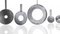
Pressure Differentials
There are a few types in this subcategory, but they all work by creating a fixed obstruction in the pipe, then making a pressure measurement before and after the obstruction. The difference of pressure relates to velocity by means of the Bernoulli equation, and with a fixed cross-sectional area and known velocity, the flow rate can easily be measured. Orifice plates and venturi (pitot) tubes fit in this subcategory.
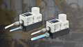
Displacement Meters
These gauges allow a fixed volume of fluid to be transmitted through the system in fixed intervals. This could be thought of similarly to a waterwheel where each little bucket holds a fixed volume. Faster rotation means more buckets in a given time, and flow can be easily measured. Many styles of gears, vanes, and pistons use this measurement concept, as long a fixed volume exists between each tooth or vane or piston cycle.

Figure 2. A positive displacement flowmeter with oval gears.
Moving the non-obstructive gauges; this category is much smaller but has many advantages because it does not interface directly with the fluid so it works well with corrosive or harmful chemicals. Additionally, these can often be more easily retrofitted on the outside of a pipe without breaking in to place the gauge in-line.
Thermal Transfer
A section of the fluid is heated with a certain amount of input power, often to a measured temperature. A second temperature sensor is placed a short distance downstream. The speed of the fluid is then measured from the outside of the system. When speed is multiplied by the area of the pipe, the flow rate is known. This method requires much more analysis of the thermal conductivity of the fluid, so it can be more difficult.
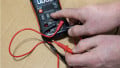
Electromagnetic
This measurement method also has many careful analysis considerations. The fluid must be conductive, and if so, it will generate a voltage if it moves through a magnetized coil outside the pipe. The rate of flow is measured as the amount of voltage, measured with a simple voltmeter.
Review of Flow Gauges
Although this is not an exhaustive list of every known type of gauge, this serves as an overview of the objective and operating principle of many types of gauges used to measure the flow rate, which allows us to know the exact amount of fluid moving through a system in a specific amount of time.