Facebook
 Google
 GitHub
 Linkedin
Introduction to Signal Conditioners
What is signal conditioning and how do you use a signal conditioner in your industrial application?
What is a Signal Conditioner?
A signal conditioner is designed to condition the incoming signal for a circuit's next level or another sensor in an instrumentation system. Signals conditioners are used to filter out noise, increase the amplitude of the low-level signal, and convert from one unit to another.

Figure 1. A standard analog signal conditioner. Image used courtesy of ABB
The input signals are often analog. These analog signals represent physical values, such as temperature and pressure. These signal levels are small enough to be detected. However, when the instrumentation circuitry can't see these signal levels, meaningful data can be lost. In addition, noise levels can also affect these small value signals and shrinks the valuable information.
The instrumentation system uses sensors with varying input signal characteristics to collect physical variables. Signal conditioners make the incoming signal, input sensor, and electronics components compatible and collaborate.
Signal Conditioners and Data Acquisition Systems (DAQ)
Signal Conditioners cannot be used as a standalone component for any application. Instead, they are used as a part of a signal processing system, such as a data acquisition system (DAQ).
Correct specifications of signal conditioning are necessary for the successful implementation of DAQ systems.

Figure 2. Servers for supervisory, control, and data acquisition system (SCADA).
Data acquisition systems are used to process the incoming physical value signals, such as temperature and pressure, to perform real-time processing. A DAQ system consists of many sub-systems, including signal conditioners.
A signal conditioner performs many functions for a DAQ and can be classified into the following categories:
- Amplification
- Filtration
- Isolation
- Linearization
Sources of Noise in Data Acquisition Systems
Noise signals are unwanted signal levels in a DAQ that alter the original signal and ruin valuable data. Noises are common in almost all measurement systems having varying sources. Let's look at some familiar noise sources in a DAQ environment.
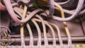
Field wiring is a common source of noise in a DAQ system. AC signals running in a conductor form a magnetic field around it. When a nearby circuit or any other signal-carrying conductor comes in the vicinity of this conductor, the magnetic field distorts the original signal, which is called noise. The noise created due to the magnetic field is called electromagnetic interference (EMI). EMI can transmit through conductors, such as cables and any physical path. EMI can also transfer by radiation without any physical direction.
Solenoid coils are a source of EMI in a DAQ system. The solenoid coil develops a magnetic field in a coil when an electrical current is applied. These magnetic fields can also induce noise in a DAQ system.
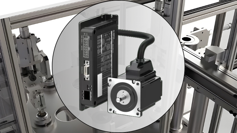
Another type is called radiofrequency interference (RFI). The RFI is the electromagnetic radiation a circuit or conductor emits when electrical signal changes rapidly. Motor and VFDs can also be a source of unwanted noise. Power cables, motors, and VFDs are also sources of noise for nearby electronic and electrical components.

Figure 3. A temperature signal conditioner. Image used courtesy of WAGO
Motors often turn on and off frequently. This frequent switching pattern draws a sudden surge of current, which generates noise. VFDs are also a significant noise originator, and the EMI is created at the rectifier stage. The rectifier converts the incoming AC to DC voltage. The rectification process creates harmonics, which contributes a significant amount of noise.
Another prominent source of noise is improper grounding. The ground is an interconnected loop at a different potential than the power source within a circuit system. The difference in potential is necessary to make the electric current flow between components in a circuit. If the ground is not established as per the design specification, the circuit readings will become erratic, causing significant noise in the output.
Correcting Noise Problems
As mentioned above, there can be many noise sources, including the functional components or systems. Eliminating noise is necessary to protect user data. For this purpose, specialized techniques and components are used. Let's look at some ways to stop the noise.
Noise Resistive Cablings
The effect of noise can be reduced by using noise resistive cables such as shielded cables and twisted pairs.
In a shielded cable, the conductors carrying the signals are enclosed by a standard shield, which can be braided, spiral design, or in a metal-coated foil. The protection minimizes the noise coupling from surrounding noise sources. The number of shielding can be increased for a high noise environment.
In a twisted pair, a pair of wires are intertwined with each other and commonly used for magnetic noise. The twisted pair cancels out the effect of noise. When the cable is exposed to noise, both lines receive an equal amount of noise. Due to the twisted pattern, the direction of noise in a wire is opposite to the other wire of a pair. The opposite direction cancels out the noise without affecting the original signal.
Proper Grounding
Improper groundings are a common source of noise in data acquisition systems. The ground in an electrical circuit is a reference potential voltage, and in most cases, it's usually at 0 volts. All the components in a course are connected to the same ground.

Figure 4. An electrical ground wire connected to ground copper bar.
If the ground is not installed or a wire breaks from ant component to ground, the noise will quickly find its way into the original signal carrying through components and wires.
Wire Route
Wire route is another essential factor in eliminating noise. When carefully selected, it can result in low noise and high throughput.
When laying cables, low voltage cables must not mix with lines carrying AC and other high-frequency noise sources such as motors and VFDs. This is done by using separate conduits for them. These cables are also required to avoid overlapping and parallel running with other wires.
Manufacturer Recommendations
When installing electrical or electronic components, manufacturers provide recommendations for the component's optimum use and application, as well as factors for canceling noise. These recommendations inform users about cable selection, running cable distance, any additional component helpful in reducing noise effects.
For example, VFDs can induce harmonics into power supply wring. The harmonics through these power cables can transfer noise in sensitive electrical/electronic components throughout the building. The manufacturer provides specific features in VFDs to prevent the harmonics from spreading out in the building. This is indicated in the relevant product brochure or datasheet.
Signal conditioners are an integral part of the data acquisition system for transferring raw data from the sensors to the next level of DAQ without altering and losing the original sensor values. They perform various functions, and, DAQ system cannot be developed without a signal conditioner.
Noise is standard in every electrical system; even the most advanced techniques cannot prevent it altogether. Noise results in the loss of essential sensory data and can alter meaningful data to affect the output of a DAQ system. There are specific techniques for preventing noise from entering the DAQ system and becomes responsible for an efficient and successful DAQ system.