Facebook
 Google
 GitHub
 Linkedin
Three-Wire vs. Six-Wire Three-Phase Motors
Three-phase motors with three or six wires have limited options for wiring, but are easier to use and have important roles to play. Learn the difference between three- and six-wire three-phase motors for low and high voltage applications.
Check out Control Automation's exclusive eBook on motor wiring

The most common types of three-phase motors are unpacked from their boxes with nine wires needing to be connected from the box on the side. This is typical of motors that can be connected for high or low voltage, and they may be either arranged with Wye or Delta internal connections. A few other scenarios exist. Motors with three or six wires have limited options for wiring, but are easier to use.
3-wire motors are completely restricted in terms of voltage input. You must use the specified input voltage or the motor will not work. On the other hand, it's super easy to connect to the supply.
6-wire motors provide a connection for both high and low voltage, but simpler (yet not as flexible in wye/delta arrangement) than the typical 9-wire style.

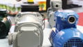
Figure 1. Three- and six-wire three-phase motors offer versatility in their use.
Most three-phase electric motors use an internal arrangement of coils that defines them as either Wye or Delta, and this is established by the manufacturer. The data plates on those motors follow a familiar wiring scheme. Occasionally, a motor appears with a different number of wires. These scenarios can be confusing without some background about the internal construction.
That most familiar scheme uses nine wires, and they can be used to connect the motor to operate equally when supplied with either high or low voltage. Typically, higher voltage is used for larger motors, but each type can have its advantages.
Are you a motor troubleshooting expert? Quiz yourself with our (no pressure) worksheet!
Three-Wire Motors
The first of the less familiar cases is perhaps the easiest to use - it only has three wires extending from the wiring box on the side. As an electrician might expect, if there are only three wires, they correspond to the input phase ‘Line’ wires.
Connections to VFDs are very simple for these motors, just connect the leads to the VFD outputs, often T1, T2, and T3. Just like any three-phase motor, the direction of rotation can be reversed just by switching two of the T-leads, be aware of that fact when installing a motor.
To understand what is happening inside, there are six coils distributed around the rotor. That way, each of the three phases will magnetize opposite sides of the rotor, providing a smooth rotation. From the factory, these motors are connected with the coils in series or in parallel, and they may be either a Wye or Delta arrangement.
The electrician cannot change any of that internal arrangement. This means the data plate may show 208-240 volts for low voltage, or it may show 440-480 for high voltage — but these motors will never be compatible with both voltages. No change to the external wires leads will be able to change the voltage compatibility of the motor.
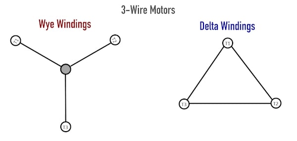
Figure 2. The internal wiring arrangement of high and low voltage three-wire motors. Each motor must be wired to a fixed voltage source according to the data plate - you cannot adjust the wiring.
Always be aware of what voltage is stated on the plate so that the VFD parameters may be set so that it is providing the proper output voltage.
The wire colors are not always consistent, so in the case of these motors, it pays to research and be sure of what kind of motor you are using. This three-phase kind of motor is not the only time that has three wires. Applying too much voltage can destroy a motor that is meant for lower voltages.
The three-wire setup may indicate any of the following types of motors: the three-phase type like discussed above, some Brushless DC motors, and many 1-phase AC motors with external capacitor connections all use three wires. There are even some standard brushed DC motors with a third wire attached to the metal case for signal noise resistance. Any of these other motors would be destroyed by energizing the coils with high or low voltage AC.
Six-Wire Motors
When the motor has six leads accessible to the electrician, they might be attached to a set of six metal screw terminals inside the motor junction box. It is common to see this set of six screws inside the cover on these kinds of motors. Regardless of whether they appear as terminals or wires, they will be referred to here as ‘leads’.
Internally, the manufacturer has taken each set of two coils on opposite sides of the rotor and bonded them together. This creates three long coils inside the motor. The two ends of each of the three coils are accessible in the junction box, giving six total lead wires.
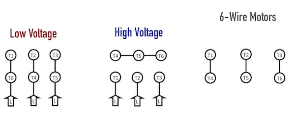
Figure 3. A six-wire motor uses three individual sets of coils which can be wired for either high- or low-voltage.
Since there are essentially three coils acting as resistors, they may be connected in series for high voltages in order to decrease the current. This would look exactly like a high-voltage setup in a normal nine-wire Wye motor.
For lower voltage, the three coils are set in a series-parallel Delta configuration, yielding lower resistance to increase the current. Again, this would look exactly like the high-voltage setup in a nine-wire Delta motor.
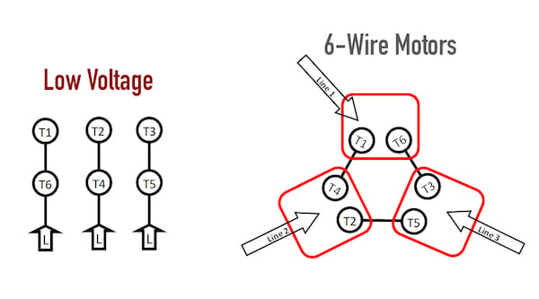
Figure 4. Low-voltage wiring for a six-wire motor. This configuration looks like a typical 'Delta' arrangement for lower resistance with higher current.
The data plate on a motor like this would often show the low-voltage wiring scheme with a Greek Delta (Δ) symbol, and the high voltage with the common Wye (Y) symbol.

Figure 5. High-voltage wiring for a six-wire motor. This motor looks like a Wye arrangement, leading to higher resistance and lower current.
This is slightly different than the nine-wire motors since in those cases, a Delta motor can be wired for either high- or low-voltage, and similarly, a Wye motor can be either high- or low-voltage. The similarity is that a single motor can be purchased that can be used in either voltage case.
Interested in more content about motors? We have plenty to choose from!
Articles:
- Comparing Single-Phase and Three-Phase Motors
- 3-phase Motor Types: Synchronous and Induction Motors
- Understanding Delta Wound Motors for Industrial Applications
- Common Motor Windings and Wiring for Three-Phase Motors
- Brushed vs. Brushless DC Motors
- Field-oriented Control (Vector Control) for Brushless DC Motors
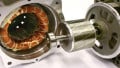
- Teardown: What’s Inside a 3-Phase Induction Motor?
Textbook: