Facebook
 Google
 GitHub
 Linkedin
Three-Phase Motors with Twelve Wires
Of all types of three-phase motors, the twelve-wire motor provides the most options for connecting based on voltage and system configuration (wye or delta). Learn the details and wiring options of these versatile motors.
Check out Control Automation's exclusive eBook on motor wiring

Three-phase synchronous motors can be purchased with a variety of wiring styles. The most common is nine-wire, but there are also many examples of motors with three, six, or even twelve wires.
Of all motor types, the kind with twelve wires is universally applicable to all connection scenarios, regardless of the required voltage or system configuration (wye or delta). Although they may seem like the most intimidating and are the hardest to connect, they are actually easier to understand than any other motor type.
Many industrial electricians will go through an entire career and never work with this type of motor. However, these motors with twelve wires are universally applicable to any three-phase power system, no matter whether the voltage is high or low, or whether the demands of the machine call for a delta or wye configuration.
Figure 1. Understanding the best motor for any application is the key to a good design.
Since they are unusual, and the number of connections is greater, it seems like these motors should be more difficult to understand. In fact, examining a typical 12-wire motor data plate reveals a complex combination of wire bondings. The good news is that this is not the case. With a little understanding of how they are constructed, these motors and the wiring connections are pretty simple to understand.
Are you a motor troubleshooting expert? Quiz yourself with our (no pressure) worksheet!
Why 12 Wires?
Inside a three-phase motor, there are three sets of coils, one directly acted by each voltage phase. They do not all have an equal voltage, but rather they divide the voltage (as series and parallel resistors) between the three input line phases.
An important note is that there are actually more than three coils, they simply act in pairs. There are, in fact, six coils distributed equally around the inside of the housing around the rotor. Each pair of coils is located directly opposite from each other across the rotor, and both of those two opposing coils should have equal voltage (and therefore equal current and driving force). The result is a well-balanced rotation from the six coils.
In a typical nine-wire motor, several of the coils are bonded internally from the factory. In wye and delta configuration, several bonds are established which cannot be disconnected by the electrician. They can simply be wired to accept higher or lower voltage, but the fact remains that for these motors, wye is always wye and delta is always delta.
In the 12-wire motor, that internal restriction has been removed. The electrician has access to both ends of all six coils, giving 12 total wire leads coming from the motor. This means that this motor can be applied in an application that demands varying factors for starting and running.
Start Types
There are two common ways that three-phase motors can be started without the aid of a digital tool such as a VFD or soft-start. Both of these ‘manual’ methods are created by simply changing the wiring to arrange the coils in different series or parallel paths to increase or decrease resistance.
First, there is ‘Across the Line’ starting. This is a simple contactor with three-phase lines that make instant contact when the coil is engaged. It’s a very simple starting method, but the motor draws much more current. In this circumstance, the motor is wired permanently for its voltage application, in other words, it should be wired for the scenario that will allow the highest current through the coils all the time. This is a delta configuration - wye will always have higher resistance, and less current.
So for the case of across-the-line starting, we would expect to wire the motor up for a high-voltage delta or a low-voltage delta configuration.
The other kind of starting method is called reduced-voltage starting. This places a lower voltage across the coils, and therefore a lower current, during a start-up phase until the motor has reached a sufficient velocity to shift to the full-speed voltage. This start-up method takes longer but it greatly reduces the start-up current.
For this kind of reduced-voltage starting, we should wire the motor for the highest possible resistance for the starting contactor, and lower resistance for the run contactor. This is achieved by using a wye winding for starting only, then switching to a delta winding for the continuous run. For this reason, this starting method is often called wye-start-delta-run.
When the supply is high voltage, use a high voltage wye winding for start-up, then a high voltage delta for the continuous run. For low voltage, it’s the same except using low voltage wye for start-up and low voltage delta for running.
Since the VFD is such a commonplace fixture in modern equipment, this VFD handles the slow ramping of the motors, and it’s becoming less common to require a motor that can be connected for the reduced voltage scenario. The 9-wire motor is the most common for VFD and soft start connections.
Wiring Examples
The wiring itself can be most simply explained by comparing these motors to their wye and delta nine-lead counterparts. We will simply examine where the wiring differs.
There are four distinct scenarios:
- Low voltage wye
- High voltage wye
- Low voltage delta
- High voltage delta
Let's look at each of these scenarios in a bit more detail.
Low Voltage Wye
Two small wye windings are placed in parallel with each other. This diagram compares the two motors, but the gray circle indicates where the bonding is internal in a 9-wire motor.
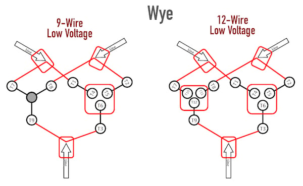
Figure 2. A comparison of nine- and twelve-wire low voltage wye windings.
High Voltage Wye
The coils are placed in series from each phase to the internal connection of three coil ends. This connection point is the only difference between the winding diagrams.
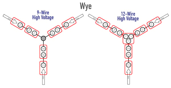
Figure 3. A comparison of nine- and twelve-wire high voltage wye windings.
Low Voltage Delta
Two small delta triangles are placed in parallel with each other. The diagrams are similar, but again, there are multiple coils bonded at T1, T2, and T3 in the case of the nine-wire motor.
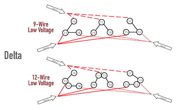
Figure 4. A comparison of nine- and twelve-wire low voltage delta windings.
High Voltage Delta
Two coils are again placed in series, but unlike the wye configuration, there is no common bonding point in the center, each set of coils is directly between two phases. This results in less resistance and higher current always for delta than for wye.

Figure 5. A comparison of nine- and twelve-wire high voltage delta windings.
Interested in more content about motors? We have plenty to choose from!
Articles:
- Comparing Single-Phase and Three-Phase Motors
- Understanding Delta Wound Motors for Industrial Applications
- Common Motor Windings and Wiring for Three-Phase Motors
- Three-Wire vs. Six-Wire Three-Phase Motors
- Brushed vs. Brushless DC Motors
- Field-oriented Control (Vector Control) for Brushless DC Motors
- Teardown: What’s Inside a 3-Phase Induction Motor?
Textbook: