Facebook
 Google
 GitHub
 Linkedin
Mitsubishi PLC to VFD Control: RS-485 Communication
This guide shows you how to set up RS-485 communication between the FX3U PLC and the FR-D700 inverter with the FX3U-485-BD. You can control speed and monitor the system using ladder logic.
Most industrial motor controls use digital communication instead of separate wires carrying digital and analog signals. Using a network approach, the PLC connects directly to the variable frequency drives (VFDs) over a serial network like RS-485. This setup makes wiring simpler, improves diagnostics, and allows you to control and monitor motor speed right from the PLC program.
In this article, you’ll learn how to set up RS-485 communication using an FX-3U PLC, an FR-D700 inverter, and the FX3U-485-BD com adapter board. The process uses Mitsubishi’s built-in inverter communication instructions.
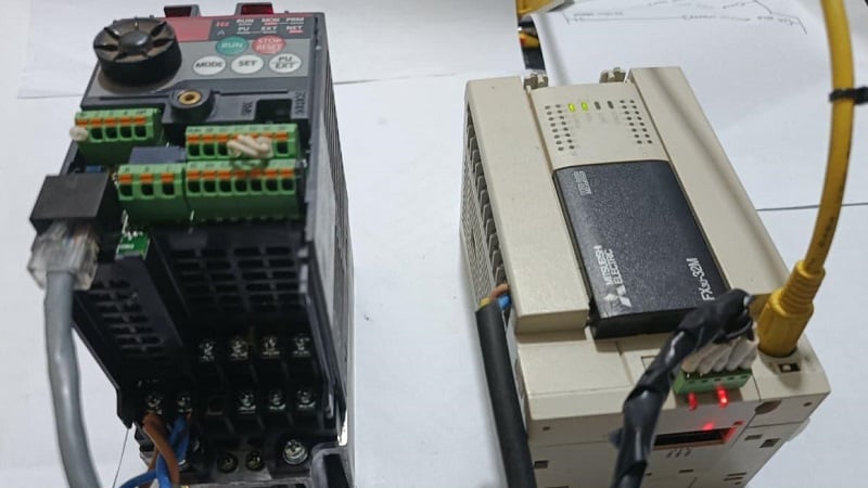
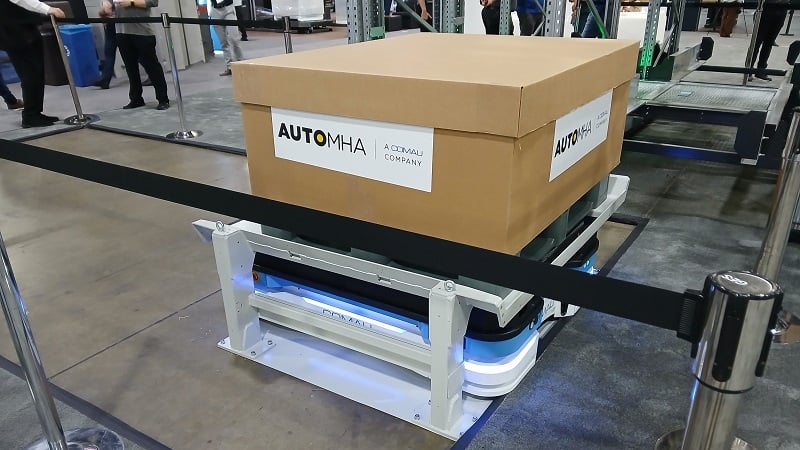
Figure 1. FX3U PLC communicating with the inverter via RS-485 for control and monitoring.
System Architecture and Prerequisites
In this example, shown in Figure 1, the setup uses the FX3U-485-BD expansion board on the FX-3U PLC, which allows serial communication through a shielded twisted pair cable. This connector attaches to a field device like the FR-D700 inverter. You will also need some basic ladder logic programming skills.
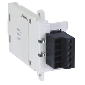
Figure 2. Close-up of the com board FX3U-485-BD. Image used courtesy of Newark
The VFD, on the other hand, has a built-in RS-485 interface that supports two control methods: the Mitsubishi inverter protocol and Modbus instructions. For RS-485 wiring, it is important to use the differential signal pairs SDA and SDB. You also need an SG connection to provide the reference to ground for stable data transmission.
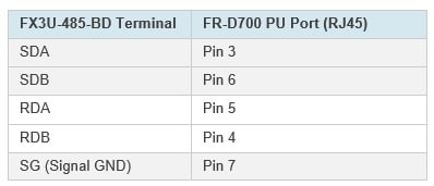
Table 1. The FX3U-485-BD and the FR-D700 RJ45 pin mapping.
Note: The connector at the VFD is an 8-pin RJ45, not a 6-pin RJ12 as is commonly used for RS-232 and RS-485 connections.
The FR-D700 Parameter Configuration
Once the hardware is connected, you need to configure the VFD parameters to accept commands through the RS-485 interface.
Some parameters can only be changed if extended parameter access is enabled. To do this, press the mode button on the VFD to access parameters marked with P and their number (Pr.).
Use the knob to scroll to Pr. 160 and set it to 0 to enable access to communication parameters.
To allow parameter changes, set Pr. 77 to 2 so the inverter can accept new settings.
After enabling access, set the parameters as shown below to match the serial communication settings in the PLC.
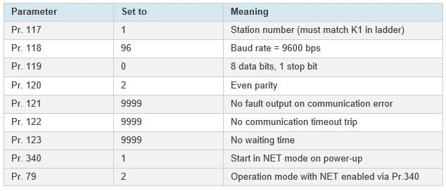
Table 2. Inverter parameter settings to establish Modbus RTU communication.
When setting the parameters, make sure to press the ‘SET’ key so the changes are applied. After all parameters are set, power cycle the inverter for the new settings to take effect. When the inverter starts, it should display ‘NET’ to show that it is ready to accept commands.
Configure PLC Communication Format
On the PLC side, you can define the communication format using the special register D8120, which controls the serial setting for channel 1 of the FX3U-485-BD communication board in the Mitsubishi PLC. This step is important because it tells the PLC which channel the expansion board uses. For FX3U-485-ADP modules, which are often installed next to the PLC, use D8120 for channel 1 communication. For channels 2 and 3, use registers D8400 and D8420. This setup makes sure both devices use the same baud rate, data format, and protocol.
Method A: Ladder-Based Configuration (Using D8120)
This is the basic traditional approach often used in older systems. This routine configures the serial communication port by moving H8097, a hexadecimal bit-coded value, into the special register D8120 that sets the serial communication format. H8097 sets a 9600 bps baud rate, RS-485 mode, 8 data bits, even parity, and one stop bit (9600-8-E-1).
Initialize the rung with M8002, which is the PLC’s first scan bit. Running this only once at startup prevents the MOV instructions from running continuously and changing the settings.
Along with setting the communication format, you can also move a timeout value to register D8129, as shown in the ladder, where a 500 ms timeout is used. If the timeout is too short, the PLC may time out before the inverter responds.
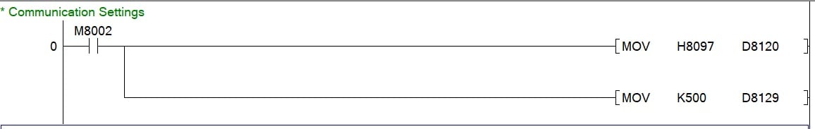
Figure 3. M8002, which is only on at startup, moves communication settings to D8120 and 500 ms delay to timeout register D8129.
Method B: GX Works Parameter Configuration
This is a more modern, cleaner approach that sets the communication directly in PLC parameters in the navigation section. The settings for this setup match the inverter’s configuration and are the same as H8097, but you do not need to use ladder logic.
Only one of these methods should be used to avoid communication errors and problems receiving responses from the inverter. Also, when using GX parameter configuration, do not write to D8120 in ladder logic. For inverter instructions like IVWR, make sure the protocol is set to ‘Non-Procedural’ and always check that the PLC settings match the inverter parameters exactly.
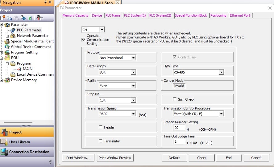
Figure 4. GX Works 2 parameter communication configuration window, an alternative to ladder-based configuration.
Distributed Frequency Read/Write Logic
You can implement distributed frequency read/write logic in Mitsubishi PLCs in two ways: time-based sequencing using clock pulses like M8012, or event-based synchronization using M8029 completion flags. Time-based methods work well for simple or single-drive systems, while event-based control is better for reliable communication in multi-device or high-load environments.
For this setup, I used M8012, a built-in 100 ms clock pulse relay, to trigger a counter. With each pulse, the counter increments, moving the steps forward automatically using comparison logic. This logic template is shown in Figure 5 below.
- When counter C0 equals 1, the PLC sends a frequency write command.
- When C0 equals 2, it sends the run command.
- When C0 equals 3, the PLC receives a frequency response from the inverter.
- Finally, when C0 equals 4, the counter resets and the read/write cycle starts again.
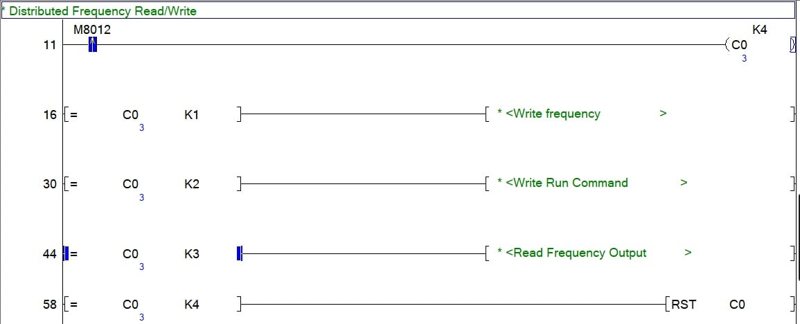
Figure 5. Template for sequenced VFD read/write logic.
Creating a Communication Sequence
Next, it is important to understand the inverter command instructions used to operate the motor. These instructions work asynchronously, so when a command is sent, the inverter processes it and then returns a response.
The FX3U provides dedicated functions to handle communication and control of the FR-D700 inverter. The basic communication cycle is to write the frequency setpoint, send the run command, read the frequency feedback, and then repeat the cycle by resetting the counter.
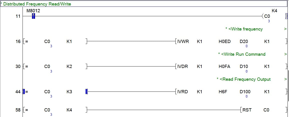
Figure 6. Counter increments after 100 ms for the distributed read/write.
For this tutorial, we use three main functions: inverter write (IVWR), drive control (IVDR), and read (IVRD). All three of these share the same structure of [IVxx s1 s2 s3 n]. For all of these commands, s1 is the channel for the 485-BD board (in this project, always 1), s2 is the destination register of the command in hex value, s3 is the variable value, and n is the station number (also always 1 in this project).
Each command is explained below.
Writing Frequency Setpoint
IVWR: s2 is the frequency register in hex (0ED), and s3 is the desired frequency value. For this project, the frequency value is stored in data register D20, which will be established in the next section.
Sending the Run Command
IVDR: s2 is the run command register (0FA), s3 is the control value (K2 for forward, K4 for reverse, K0 for stop). The control value is stored in data register D10 (also established in the next section).
Reading Feedback from the Inverter
IVRD: s2 is the output register (for this project, we are reading the output frequency 6F), s3 is the variable that is designated to store the incoming data being read (in this case, the frequency is stored in D100).
Setting Frequency and Control
The final step is setting the desired frequency, and then running/stopping the motor. Each of these commands is set using an MOV command driven by a contact (or external pushbuttons, if you wish).
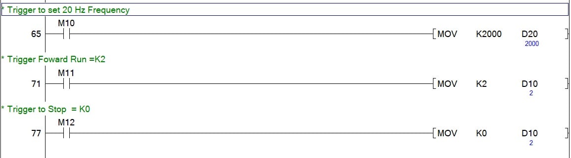
Figure 7. Trigger for frequency and run/stop commands that move data to registers associated with the inverter instructions.
As we saw in the previous section, D20 is the frequency value, which we are setting to 2000 (scaled in the motor to 20.00 Hz). D10 is the control value, which may be set to 2 for forward run, or 0 for stop.
Verify Hardware Indicators and Testing
Once communication is set up and the control logic is in place, you can check that everything is working correctly at both the software and hardware levels. Check the LEDs on the FX3U-485-BD board. The SD (send data) and the RD (receive data) LEDs blink when the PLC is sending/receiving data from the inverter. If only the SD LED is blinking, the PLC is sending data, but the inverter is not responding. Possible causes include reversed wiring polarity, wrong station number, mismatched communication settings, or the inverter not being in network mode.
Turning to the hardware setup, start the PLC and watch for the SD LED to blink. Trigger M10 to set a 20 Hz frequency, then trigger M11 to send the run command (K2). Check for a blinking RUN LED to confirm the command. Observe the frequency output in D200. If the value is zero and the RUN LED is not on, check the wiring and communication settings. These final steps connect the program design with real-world operation.
Although there are many variations of RS-485 implementation across manufacturers, the general principle is fairly similar. However, it is important to consider these variants, as most communication issues come from differences in physical setup and control functions, not from the logic.
All uncredited images used courtesy of the author
Related Content