Facebook
 Google
 GitHub
 Linkedin
How to Use Analog to Digital Converters in a Control System
Using an ADC can be very useful when dealing with analog devices in microprocessors, and a necessity when adding analog devices to an industrial controller. But once you connect the hardware - what next?
Analog vs Digital Signals
Digital control systems (such as PLCs) and microcontrollers operate at a fundamental level with 1’s and 0’s, but in the real world, we have positive and negative, and both very large and very small numbers. Digital and analog are presented as opposing options in control systems, for good reason.

Figure 1. Analog signals and digital signals are both common in industry but are handled by entirely different circuitry. Image used courtesy of Canva
An analog signal usually comes in the form of 0-10 VDC or 4-20 mA, but other common ranges include 0-5 or -10-+10 VDC, or 0-20 mA. The analog signal can exist at any level between those min and max values. A digital signal (often called ‘discrete’) is quite simply 0 or 1, like a light that is on or off with no in-between. Within our control system, all digital values are stored as data types like a Byte, Integer, Word, or Double Word if they are whole number integers, and a float or REAL if the number has a decimal point, like the value 5.387, which is not an integer. It is important to note that both integers and floating-point values are both digital representations.
What is an Analog to Digital Converter
The purpose of an analog to digital converter or ADC is right in its name, it takes an analog signal like temperature, pressure, or any signal voltage or current, and converts it to a digital equivalent representation. The analog signal may be between 0 and 5 volts, and the converted digital signal is in the form of an integer, and can range from 0 to 1024 or 0 to 65536. In some ADCs, usually accomplished with a software calculation, the digital value may instead be a floating-point number equaling the actual voltage value, for example, the previous 5.387 volts.
How Does an ADC Work
There are many different kinds of ADCs on the market and mostly they come in the form of integrated computer chips. The inner workings of these chips are quite complicated, there are a few strategies for completing the task. Some ADCs will charge a capacitor using the varying analog input, and use the clock cycles of the processor to determine how long it takes for the capacitor to completely discharge. This number of cycles results in an integer value. As the capacitor and clock cycles change so does the maximum resolution of the ADC.
Another common method for basic conversion at a high speed (called ‘flash’ conversion) is to use a network ‘ladder’ of series resistors and compare the input analog value with individual voltage increments. Other methods exist with the use of amplifier and comparison solid-state electronics.
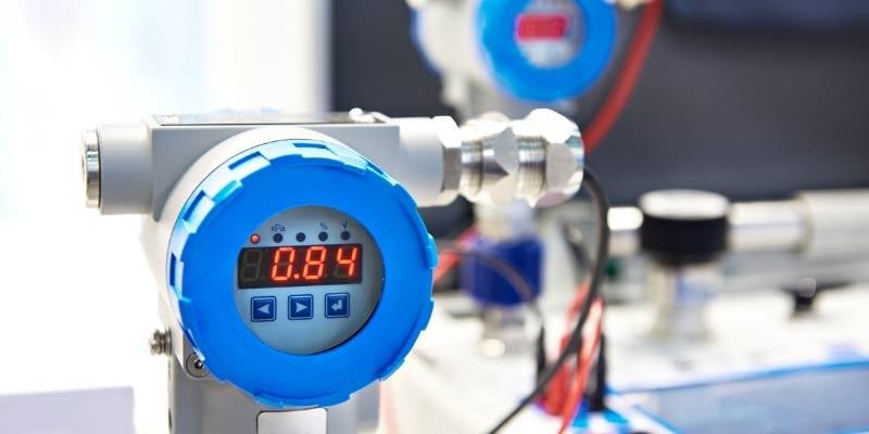
Figure 2. Analog signals are often used in fluid systems with pressure, temperature, and flow rate always being analog signals. Image used courtesy of Canva
Types of ADC
There are many different types of analog to digital converters on the market today. Some come in the form of chips, but for the industrial engineer, the converters are more likely to be integrated directly into the microcontroller or system controller in your current project. These will likely be in the form of analog input modules for a PLC or remote I/O system. Even VFDs and motion controllers will almost certainly have one or two built-in analog inputs.
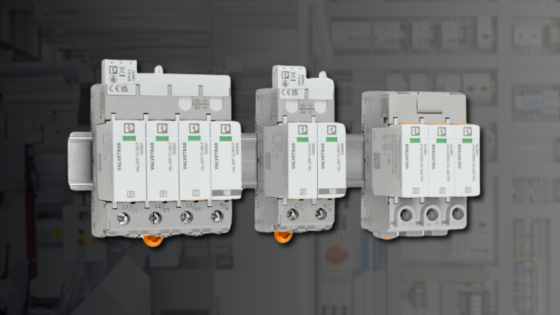
There are other ADCs that will convert raw analog values into an industrial protocol to be sent across a network. Some manufacturers make analog to IO-Link converters, while others may produce analog to ethernet converters which could be Ethernet/IP or ProfiNet. Scaling may or may not occur in the converter, which means the transmitted value may be in the range of 0-1024, or 0-65535, or the value may represent the original voltage of the sensor, between 0-10 volts. Each converter will be slightly different and you will need to refer to the datasheet to determine the scaling that needs to be done in your control system.
Using Your Analog to Digital Converter
Once you have selected your analog device and your analog converter you can wire it according to the manufacturer’s instructions. You will need to know the min and max value of your sensor and the bit resolution of the ADC so that you can scale the input accordingly.
ADC Resolution
The resolution of any ADC is represented in bits; 16 bit, 10 bit, and 8 bit for example. These values represent the number of slices into which the analog signal will be divided. For example, an analog signal of 0-10 VDC using an ADC with 10 bit (2^10) resolution will yield a digital value of 0 to represent 0 VDC, and 1024 to represent 10 VDC. This means 5 VDC will have a value of 512 (1024/2). As long as your analog signal is linear this relationship can be scaled into an algorithm and applied to any value of the incoming signal.
Algorithm to Convert Analog Values
If a calculation is required to obtain the actual real-world value of the sensor, it can be accomplished in two ways, either with built-in functions or manually.
If the system is a modern PLC or microcontroller, it is likely to have a mapping function (likely called ‘map’ or ‘scale’), where a command or function block compares the current analog value to the minimum and maximum process values and calculator the current value. In the background, this process is a linear regression which can be done quite easily with a manual calculation if needed.
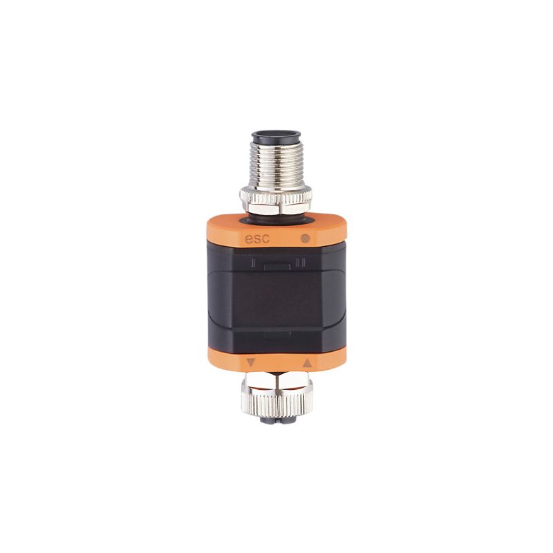
Figure 3. Converter between analog signals and an IO-Link Field bus. Image used courtesy of IFM
Let’s use an example of a temperature sensor that measures 0-100 °C with a voltage output of 0-5 VDC, and a bit resolution of 10 bit for our ADC (0-1024). We would need to set up a ratio comparing the max digital value over max voltage to the current digital value over current voltage.
$$\frac{Digital~Value~of~ADC~at~Max~Voltage}{Max~Voltage~of~Sensor}=\frac{Current~Digital~Value}{Current~Analog~Input~Value}$$
Using the values from our example:
$$\frac{1024}{5~VDC}=\frac{X}{2.0~VDC}$$
$$2.0~VDC\times\frac{1024}{5~VDC}=x=409$$
Using this newly-calculated digital value, whether obtained by calculation or automatically by the controller, we can similarly determine the actual real-world value of the temperature.
$$\frac{Max~Temp~of~Sensor}{Digital~Value~of~ACD~at~Max~Voltage}=\frac{Current~Temperature}{Current~Digital~Value}$$
$$\frac{100^{\circ}C}{1024}=\frac{X}{409}$$
$$409\times\frac{100^{\circ}C}{1024}=X=39^{\circ}C$$
Where 39 degrees is the actual temperature at the sensor.
Here is illustrated another important detail about real-world data conversion. From the original data, a sensor reading of 2 volts should yield exactly 40 degrees, but through data truncation with integers, only whole numbers can be obtained. This may skew the final calculations, as they did in this case - an error of 1%.
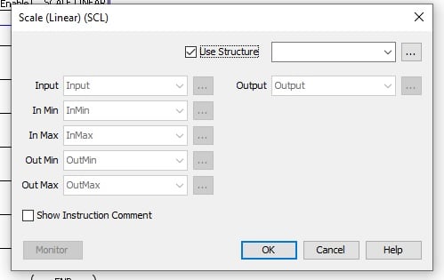
Figure 4. Example of a scale command using linear regression. Both the input minimum and maximum, as well as output minimum and maximum, must be known, and the analog value can be used as the process input.
Conclusion
Using an ADC can be very useful when dealing with analog devices, and is a necessity when adding analog devices to a controller. When using ADCs located close to the sensor we can facilitate shorter runs of specialty signal cables which will reduce electrical noise within our system. By using an analog to industrial protocol converter you can save money and time because installation is as easy as plugging in a cable, and less hardware needs to be purchased, provided you have the required networks already set up in your system.