Facebook
 Google
 GitHub
 Linkedin
Advanced Scaling Techniques for PLC Analog Quantities
Configuring analog signals into usable digital quantities is accomplished by scaling function inside the PLC, which, along with analog signal wiring, is important to understand.
In a previous article, we covered the need for analog signal scaling for many natural quantities like sound, light, and temperature. The process involves establishing a relationship between a physical quantity and an electrical signal: voltage or current. While the resulting linear equation can be programmed into any PLC (as can some non-linear relationships), most brands offer predefined functions to achieve the same goal. This article will cover some of these functions and expand on voltage and current analog signals.
Voltage and Current Analog I/O
First, let us discuss the two types of analog signals: voltage and current. Regardless of what kind of analog I/O is used, the mathematics behind the scaling process is the same. A voltage or current I/O may be chosen depending on the characteristics of the controlled system.
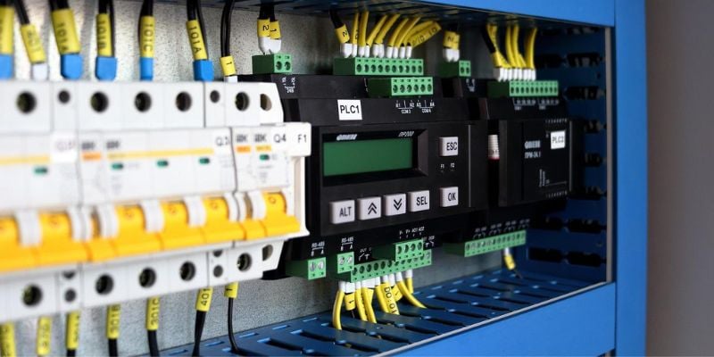
Figure 1. Electromagnetic interference, often from high-current lines, affects voltage sensor signals significantly. Image used courtesy of Pixabay
Voltage analog signal transmission is reliable only at short distances. The longer the cable, the more significant the voltage drop due to the increased resistance of the wiring. The most common operating range of a voltage I/O is 0 to 10 V, so a change of even a fraction of a volt can cause serious signal inaccuracy.
Current signal transmission does not suffer from degradation at longer distances, being a constant-current output that adjusts its own output voltage as the resistance of the wire length changes. In addition, most analog signaling uses differential-pair voltage levels, erasing many EMI effects that would influence voltage signals. As a result, it is an extremely popular form of analog signal transmission.
Besides supporting longer distances and being more resistant to noise interference, current signals also have a safety feature called “live zero”. The standard operating range of a current signal is 4 mA to 20 mA. The bottom limit at 4 mA means there is still output from the sensor even if the physical quantity is at its lowest value. In contrast, the bottom limit of a voltage signal is 0 V, and there is no absolute certainty that the 0 V is caused by a sensor reading or a broken connection.
Current signals also need less power than voltage signals and allow the connection of multiple devices in series because voltage drop is less of a factor.
All these are important design considerations, but they also affect scaling. For example, if we have a voltage signal subject to electromagnetic noise, the sensor output levels would be inconsistent. The resulting equation would be incorrect if we scale the sensor under these conditions. The signal behavior would appear nonlinear but would be a result of noise.
Scaling Functions and Libraries
In this section, we will describe the standard functions for signal scaling available within Siemens, Rockwell Automation (Allen-Bradley), and Beckhoff, and similar examples are found in virtually all other platforms.
Siemens - TIA Portal
We need the instructions SCALE_X and NORM_X to scale an analog signal in TIA Portal. First, NORM_X normalizes the function’s input and returns a value between 0.0 and 1.0, depending on the MIN and MAX parameters setup. In other words, this function returns a number representing the percentage that the input is for the operating range, which is helpful because it makes the scaling process independent of the physical quantity unit of measure.
The normalized output then becomes the input of the SCALE_X instruction. SCALE_X converts the input into the data type of the output, and the conversion factor depends on the MIN and MAX values of this instruction.
The functions work for both input and output. For the input, NORM_X will normalize the readings from a sensor, while for the output, NORM_X will do the same for the physical quantity in its original unit of measure.
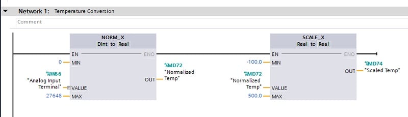
Figure 2. NORM_X and SCALE_X for scaling an analog input. Image supplied by Control.com
Rockwell Automation (Allen-Bradley) - RSLogix 500
RSLogix 500 comes with the SCP function, known as “scale with parameters”. SCP is very straightforward. The input MIN and input MAX define the operating range of the input variable, while scaled MIN and scaled MAX define the same range, but in the units of measure of the output. This is equivalent to specifying two points from a straight line.
Rockwell Automation (Allen-Bradley) - RSLogix/Studio 5000
The most recent version of Rockwell’s software, designed for Control and CompactLogix platforms, does have options for scaling, but they must be downloaded and implemented as Add-on Instructions (AOIs). These are similar in function to the SCP implementation of RSLogix 500 and are available from the Rockwell support site. Alternatively, a user-defined AOI can be defined, as in the example in Figure 3 being named "SCLE", with a simple temperature conversion scale.
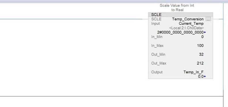
Figure 3. Add-on Instruction (AOI) defined in Rockwell’s Studio 5000 to convert between temperature scales. Image supplied by Control.com
Beckhoff - TwinCAT
Beckhoff does not offer a scaling instruction. Instead, the straight-line equation must be coded into the PLC program, which is easier to do when using structured text.
Analog Signal Wiring
Correctly wiring an analog device is another crucial step to proper calibration and functionality. Unlike digital I/O, analog I/O always comes with at least two wires.
For current I/O, the current is calculated based on a known supply voltage applied to a resistor with a known value. This results in a closed-loop circuit formed by the I/O module and the analog sensor. Based on the closed-loop design, there are three main types of analog devices: 2-wire, 3-wire, and 4-wire. The names indicate the number of wires connected to the I/O of the PLC.
A 2-wire device is the most simple. One wire is the power supply, and the other one is the ground.
A 3-wire device introduces an external power source and isolates the power circuit from the current measurement secondary circuit.
A 4-wire device follows a similar concept as the 3-wire device but further isolates the power circuit by isolating the ground connections.
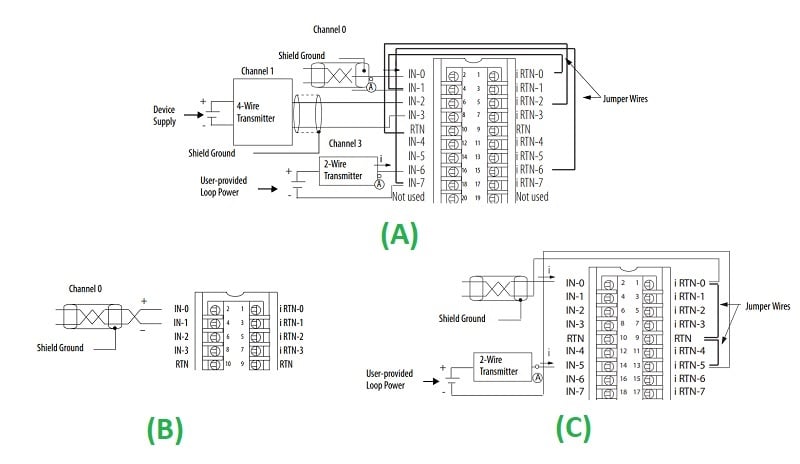
Figure 4. Different types of analog sensors are based on the number of wires. One module example wiring is shown with differential current (A), differential voltage (B), and single-ended current (C). Single-ended voltage simply consists of the voltage signal to the input terminal, all referenced to the control system ground. Image derived from Rockwell Automation literature
Wiring is more straightforward for voltage sensors and outputs because they are always 2-wire. One wire will be the voltage output, and the other one will be the ground connection.
Summary
Every PLC brand has consistent methods for establishing the sensor connection with an analog input as well as the process for converting the analog quantities into digital representations of values. It’s important to learn the process for each hardware and software to quickly resolve measurement errors and calibration processes.
Related Content