Facebook
 Google
 GitHub
 Linkedin
Inside Rockwell Automation’s Factory Where Automation Is Built
Join Control.com for an inside look at the Rockwell Automation HQ in Milwaukee, WI, and check out a fully automated assembly line. Plus, a preview of new product tutorials, coming soon!
A foggy day in Milwaukee almost obscured one of the most iconic downtown views in the Upper Midwest. The famous clock tower, rising above the original headquarters of the Allen-Bradley company, was barely visible through the mist. During the tour, I explored a robotic assembly line producing motor contactors, along with new product developments including waveform-aware motor starters and in-cabinet single-pair Ethernet networking. The facility highlights how integrated robotics, modular conveyance, and industrial control technologies combine to automate the production of automation hardware itself.

Figure 1. The famous “Polish Moon” clock tower atop the Rockwell Automation HQ. Image used courtesy of the author
Regardless of the weather, the Control.com engineering team was thrilled to visit the assembly line of some popular motor control products, see inside, and learn about the tech working behind the scenes to produce more of the tech we see in thousands of control panels around the world. Before the tour, I learned a bit more about two recent updates to the Rockwell Automation catalog.
Motor Starting - Waveforms
The M100 line of motor starters is a new take on the age-old electromechanical contactor. First, a tremendous advantage to safety and device longevity is the ability to monitor the waveform. Without monitoring, the contacts simply switch open or closed the moment the control (coil) voltage is changed. If the incoming waveform happens to be at full current when that switch action occurs, a spark will occur. This spark causes pitting to the contacts, reducing lifespan and increasing losses. It's also very dangerous in certain explosive environments.
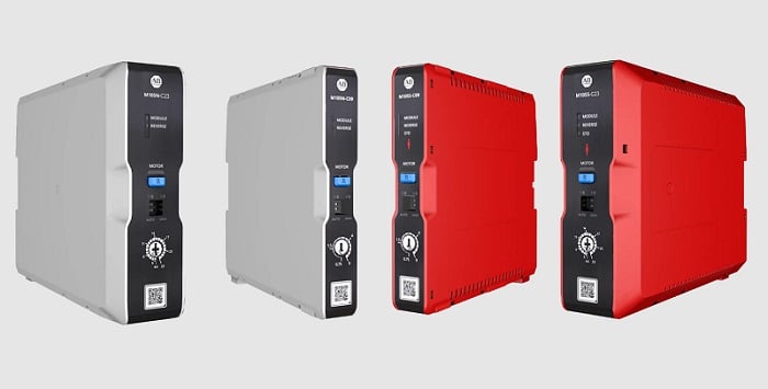
Figure 2. The M100 motor starters with waveform detection. Image used courtesy of Rockwell Automation
When we can measure the point of the waveform accurately, the switch can occur at the exact moment when the current between phases crosses zero. One step further, the three contacts can be activated at different times, since 3-phase voltages cross zero at slightly different times. The waveform detection is most critical when the switch contacts open, so the M100 is designed to monitor and adjust the timing of the open, not the timing of the closing action.
These starters also include integrated reversing capabilities and a set of solid-state contacts to monitor and protect against overload conditions. The small size also ensures the devices occupy a fairly small footprint in the control cabinet.
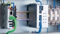
In-Cabinet Networking
I’m very excited about this product development. Last year, Rockwell announced a revolution in cabinet construction: the Ethernet/IP In-Cabinet solution. Caution: when we use the word “revolution” in this industry, we really have to take that with a grain of salt, at least I sure do. But in this case, it’s simply a matter of migrating signals from a bunch of individual wires down to a single bus cable.
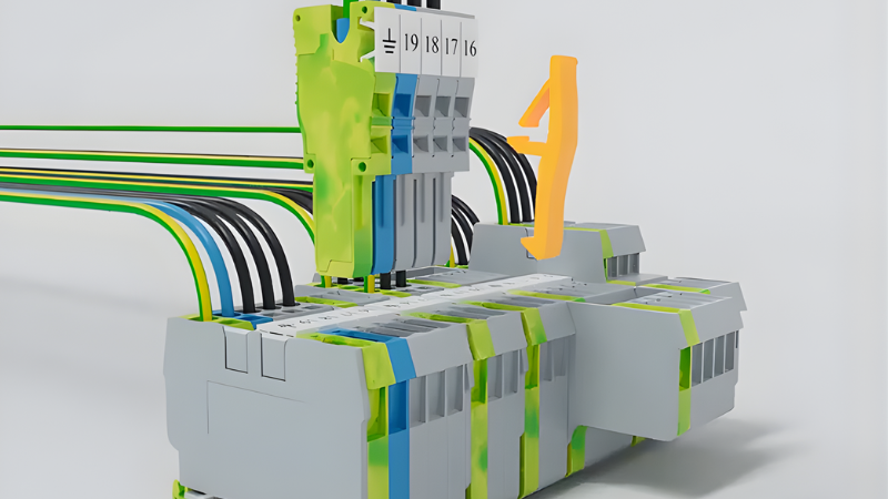
The general idea goes like this:
- The PLC connects to a small gateway via Ethernet. The gateway is powered by a 24 VDC supply.
- The gateway is connected to a flat ribbon cable with a few conductors.
- Two of them provide a dedicated single-pair Ethernet (SPE) fieldbus.
- Another pair of conductors provides power to the network nodes.
- A third conductor pair provides power for the field devices, like starter coils and illuminated pushbuttons.
- Finally, a single conductor is used for node identification
- Each new node is connected to the flat cable with punch-in adapters.
- Even after commissioning, new devices can be connected at any intermediate point by punching in a new adapter.
At the end of the day, we have replaced dozens of custom-cut I/O wires and I/O modules with a single daisy-chained ribbon cable spanning multiple devices.
Further benefits of SPE networking include monitoring the current and voltage of the starters, dynamically changing the colors of illuminated switch operators, and diagnosing faulty devices by ID and location at any time. Control.com will be publishing tutorials on this new networking concept very soon!
New PLC and Software
Another recent noteworthy announcement is the updating of the Connected Component Workbench (CCW) software to FactoryTalk Design Workbench. This software works with Micro810 and with Ethernet versions of the Micro800 series (those with Lx0E part numbers; the E stands for Ethernet).
Equipped with these products, we’ll also be publishing tutorial articles to help you get started with the new software and PLCs.
On With the Show!
Although the products have tangible appeal and build excitement for future content, we really came to see the facility. On one of the upper levels of the building, a production line assembled the 100-C series of motor contactors, a modular device with various SKUs for coil voltage, overload protection, maximum current, and other ratings.
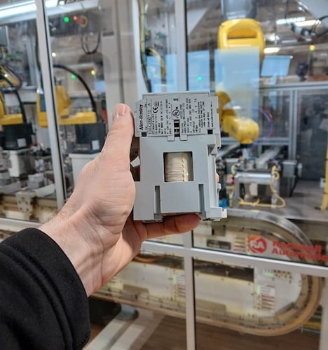
Figure 3. A 100-C09 contactor in front of the assembly line. Image used courtesy of the author
The assembly line, fabricated in large part by Calvary Robotics, incorporates the iTRAK modular conveyance system, along with plenty of Rockwell controllers, drives, and I/O, to progress the product along the assembly stages.
The assembly stations themselves are nearly all operated robotically. Depending on the needs, the robots are gantry, SCARA, articulated, or delta styles, some floor-mounted and others mounted above the line. Specialized grippers pick each piece as it builds the contactors according to the order specifications.
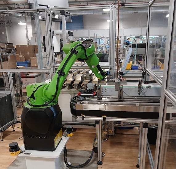
Figure 4. Packaging the finished contactors before shipping. Image used courtesy of the author
“How many pieces go into a standard contactor?” you may ask. Great question. Below is a picture of the very same contactor that I brought with me to visit the assembly line. A sort of homecoming, if you will.
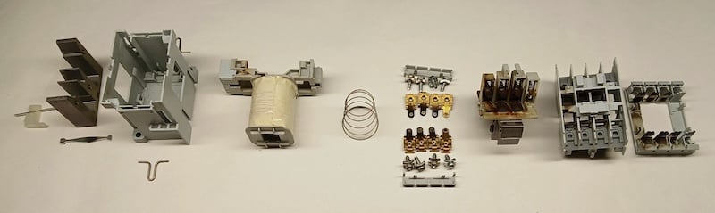
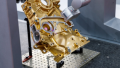
Figure 5. Sub-components of a 100-C series contactor. Image used courtesy of the author
Please pay careful attention to the components on the right-hand half of this image. These pieces are the metal switch contact components and the housing around them. Note that three of the four contact sets (the load contacts) and the plastic are marred by dark scorch marks. This takes us back to the earlier discussion of sparking and zero-voltage waveform monitoring. This image is a great illustration of what happens inside a standard contactor and shows why waveform monitoring can offer a significant advantage in longevity.
What’s Next?
Stay tuned for our upcoming tutorials, where we’ll uncover installation details of the in-cabinet Ethernet solution and the new PLC and software versions. Thanks again to the Rockwell team for hosting our visit, and we’re already looking forward to the next time we can drop by to see the clock tower in all its shining glory on a sunny day.
Related Content