 Facebook
 Google
 GitHub
 Linkedin
Arduino PLC IDE Tutorial 2: Analog I/O and External Devices
Previously, we described how to use the new Arduino PLC IDE to control discrete devices. This tutorial will describe how to connect various peripheral equipment (VFD and robot) using analog inputs and outputs.
See our previous article that shows how to use the new Arduino PLC IDE to control discrete devices:
How To: Use the Arduino PLC IDE to Build Basic Ladder Diagrams
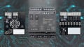
In the last tutorial, we used basic ladder diagrams to control discrete devices using common function blocks from the IEC 61131 standard with the Arduino Portenta Machine Control (PMC) platform. Now it’s time to connect external devices to the PMC, as would be expected in any industrial environment.
In this example, we will assume a small machine center without any networking requirement.
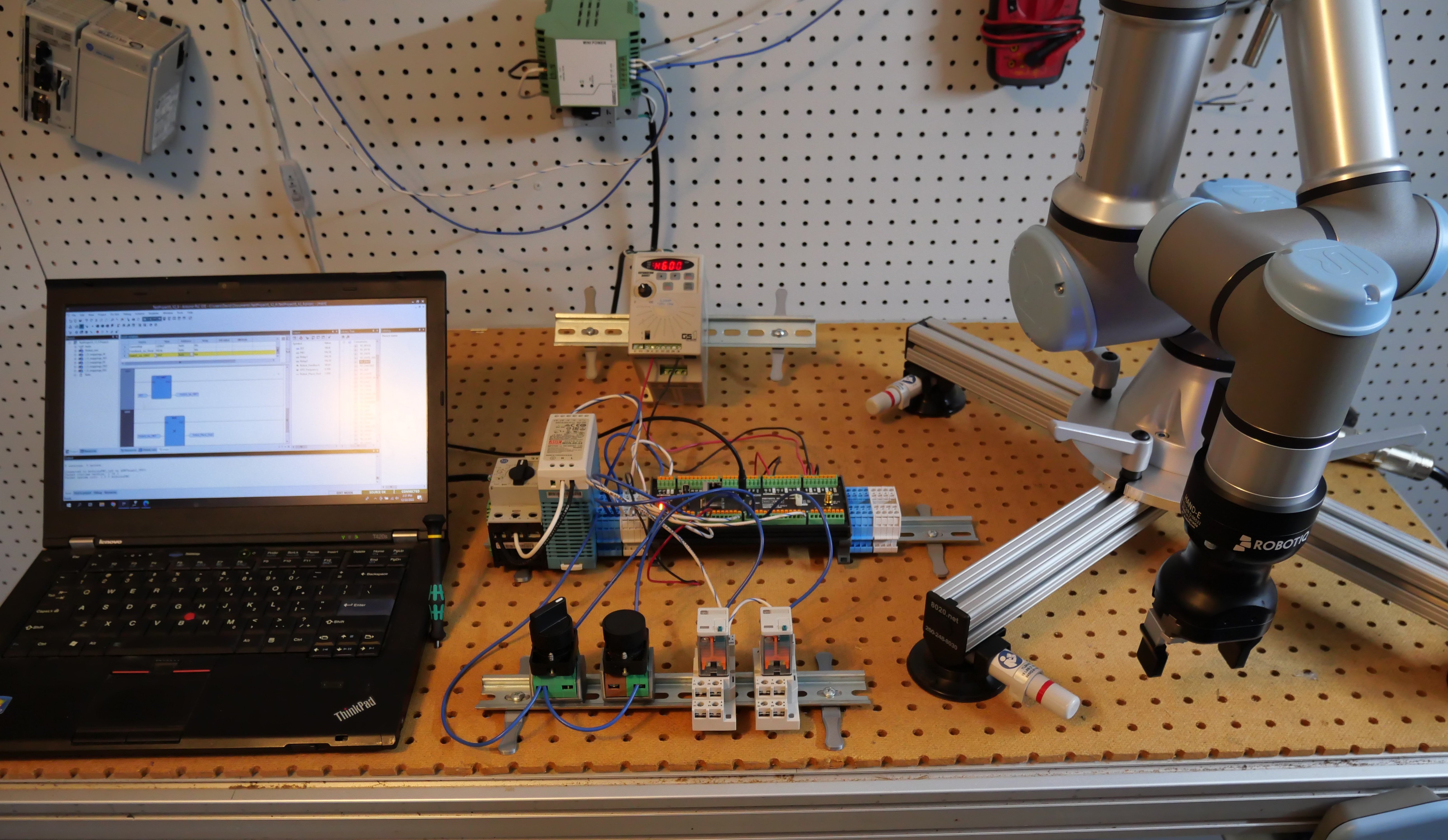
To set the stage, we will simulate a simple machine tending task. A small infeed conveyor driven by a VFD will present parts to the robot, which will then pick and place the parts in one of two machines, depending on the type of part. We'll only discuss the PLC, the VFD, and the robot, since those are the components that accomplish the communication.
The speed of the conveyor must also be controlled, otherwise the parts might arrive too quickly and stack up while the robot is performing a motion program.
Therefore, we need an itemized plan to ensure we include all of the steps:
-
The robot must be commanded to begin the pick-and-place routine.
-
Once the routine is begun, the speed of the conveyor should decrease.
-
The robot must place the object in the correct location (depending on part type).
-
Once the routine is finished, the conveyor can be set back to normal speed.
How to Connect the Arduino PLC to a VFD
First, we configure our VFD to receive its speed command via the analog input. In this case, we will use the 0-10 V signal, but both the PMC and the VFD can be configured for milliamps quite easily. What is the benefit of the milliamp signal? Preservation of signal quality is one of the primary reasons, but for this example, we’ll stick with voltage.
Analog communications must have both the signal and the reference wire. Red/black wire pairs will be used for all analog signals in this hardware setup. If you want the best signals using 0-10 V channels, it is advised to use twisted-pair shielded wire sets.
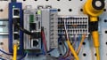
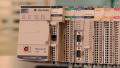
This GS1 series VFD has its analog in (AI) and common (CM), which are matched to the PMC’s own AO0 (%QD1.0) and GND beside it.
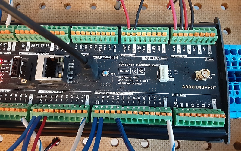
Figure 1. Added wires in red from previous tutorial: Digital Out 1 to robot, Analog In 0 from robot, Analog Out 0 to VFD, Analog Out 1 to robot.
(Click to see a higher-scale view of wiring for I/O connections)
For simplicity, the keypad of the VFD still controls the on/off operation of the VFD, but in reality, it might be a separate digital signal.
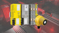
Connect the Arduino PLC to a Robot
Not all robots are the same, but they do all have the ability to accept inputs and deliver output signals. In our case, we simply need one digital input, one analog output, and one analog input.
Understandably, there are alternative methods to complete the task, but using the analog output will allow us to investigate how to use the PMC’s analog inputs.
-
PMC’s digital output DO1 (%QX0.1) connected to robot’s DI0
-
PMC’s analog output AO1 (%QD1.1) and GND to the robot’s AI0 and GND (AG)
-
PMC’s analog input AI0 (%ID1.0) and GND to the robot’s AO0 and GND (AG)
First, in accordance with the previous article, set up one digital output to act as the start command for the robot, as shown below.
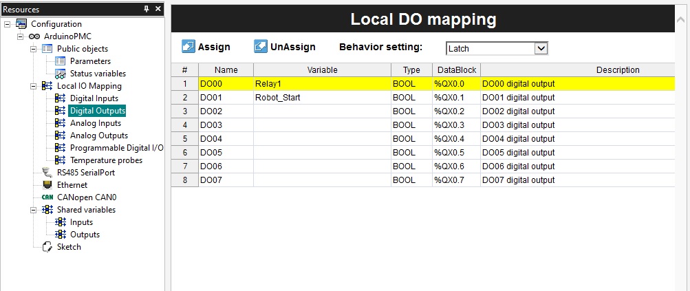
Figure 2. Added Digital Output tag (Robot Start)
Set up the Analog I/O Tags in the Arduino PLC
Since we have three analog connections established, we must now create three matching tags in the I/O database.
Fortunately, this process is quite simple. Navigate to the ‘Resources’ tab on the left sidebar, and access first the Analog Output (AO) listing. The first output, AO0 with address %QD1.0, is attached to the VFD for speed control, so name this one “VFD_Frequency”.
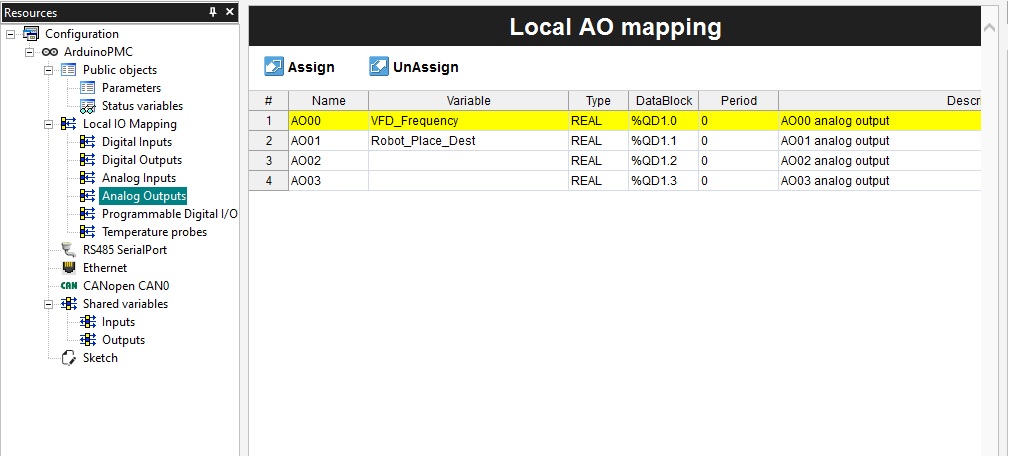
Figure 3. Analog Output tags
The second output (%QD1.1) will direct the robot to choose from multiple drop locations, so name this one “Robot_Place_Dest”.
The analog input (%ID1.0) is received from the robot, so we will label this one ‘Robot_Feedback”.
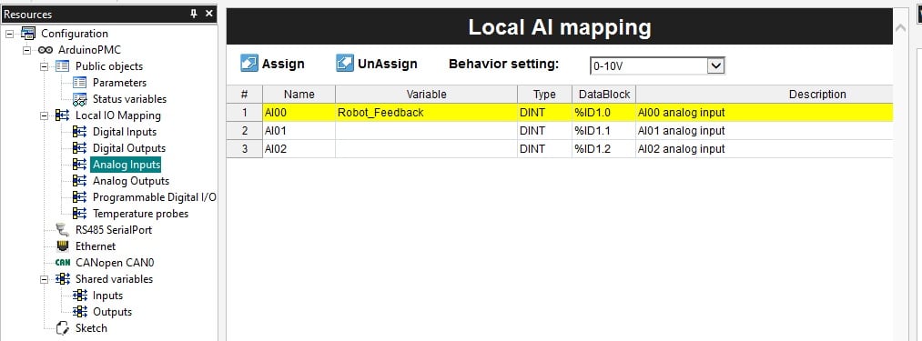
Figure 4. Analog Input tags
In the case of analog channels, a drop-down menu will select the behavior type of the signal, voltage or current. In this example, we will use voltage for all channels, but both VFD and robot can accept and send current signals just as easily, so this example could make simple use of any signal type.
Data Types for Analog Signals
Analog inputs and outputs must be differentiated. This can be tricky for experienced PLC users because various PLCs will use different values to represent the full-scale signals sent and received.
For example, those familiar with Arduino Uno boards will immediately recognize that analog inputs (analogRead) can range from 0-1023. Analog outputs (analogWrite) can range from 0-255. For PLCs such as the Siemens S7-1200, analog inputs (used in a normX command) and outputs (used in a scaleX command) will range from 0-27648.
Thus, the question is: what is the value range we should use in this Arduino PLC IDE?
Analog Input Scaling
The analog input values correspond to a range of 0-65535 to represent the full 0 to 10 V input span, with some extra left over for overvalues. When I tested the signal with my input from the robot, the maximum value I received was 58500, so I considered this value as the maximum for my program.
The data type directly from the analog input is a double integer (DINT) but sometimes must be converted to be of use for other functions.
In our scenario, the analog input from the robot will be directly translated into an output voltage. The problem in this case is that the input is an integer value (no decimal places) but the analog output, as we’ll see shortly, does require the decimal precision for fractional values of a volt output. As a result, we will need to convert the DINT to a REAL for this to be a useful program.
This conversion from one data type to another requires a couple of intermediate tags, or variables. That way, we keep the original input values, this intermediate value, and the final output to the analog ports. These intermediate value tags are shown below.
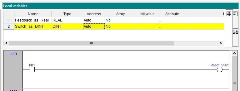
Figure 5. New local variables used for converting data
Analog Output Scaling
The analog outputs are quite simple compared to inputs. As opposed to arbitrary integer ranges based on the precision of the A/D converter, the output spans from 0.0 to 10.0. These are REAL floating point decimal values, so the data types must be designed to match.
Programming: Analog Output to Robot Controller
In our scenario, we must choose the robot placement location by sending a variable signal from the PLC. We’ll use our selector switch to simulate a sensor value which will toggle between one object and another. In a real system, vision systems, barcodes, and discrete sensor arrays provide all kinds of product information for variable processes. In our system, we’ll keep it to two options only.
When the BOOL value is received by the digital input, we will convert this to a 1 or 0 using a TO_DINT command, then multiply that value by a non-zero value less than 10 (with a MUL command), yielding a product of either 0 or 7 based on the value I arbitrarily chose here, depending on the switch position. This 0 or 7 will be directed to the analog output AO1.
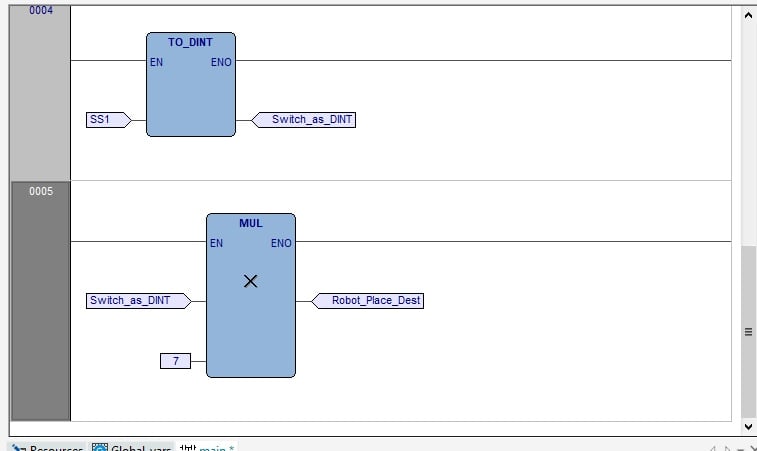
Figure 6. Logic to use selector switch (SS1) to drive analog output with either 0 or 7.
Perhaps this is overkill for a program that will only choose between two positions, but the end goal is to provide the ability, with one of those sensor arrays or barcode scanners, to send any number of voltage ranges, which the robot could translate into a wide range of place positions, all while consuming only one signal port.
Programming: Analog Input to Analog Output
In the final step, we must receive an analog feedback value from the robot, then ‘forward’ this value to the VFD. Why not just send the robot’s analog value right to the VFD? Good question. We could, if that robot was the only influencing factor on the conveyor speed, but the entire purpose of a PLC is a central ‘traffic control tower’ to be responsive to the entire ecosystem of devices surrounding the product and equipment. Likely, that robot is not the only influencing factor in the real world.
First, we examine the analog input port and see that it provides us with an integer value. We must convert this to a floating point value using TO_REAL to be useful for high precision to the output.
Without this conversion, we will only send voltage outputs of 1, 2, 3, 4, etc volts. Whole numbers only. But we can do better.
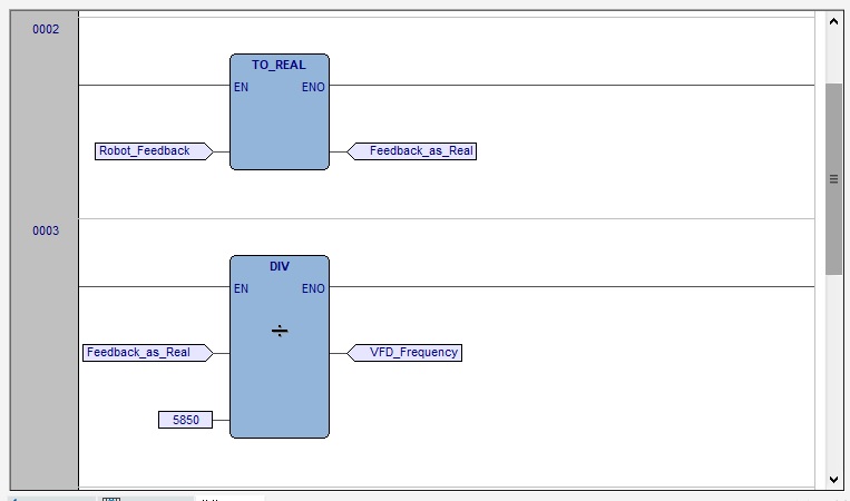
Figure 7. Logic to use robot feedback to control the VFD_Frequency.
After using a conversion to a REAL value, we use a DIV command, dividing the analog input (0-58500 in my case) by 5850 to yield an output of 0.0-10.0, which is really just a simple linear scaling method. The destination location of the DIV command is simply the analog output VFD_Frequency.
Program Summary
We have now designed a program that can take in digital and analog inputs and manipulate those values mathematically to provide variable analog outputs to external equipment like a VFD and a robot.
For a quick 'summary' glimpse into our final system at work, have a look at the video below.
Want to test your knowledge of PLCs? You think you N.O. a lot about ladder logic? Are you a normally-open or normally-closed minded engineer?
Check out our PLC Programming worksheet!


I love Instrumentation and everything in Control Automation
I already Feel great coming across this platform.
Hi, good write.
I have transducer from electrical panel connected to A0 and not reading any decimals. Must I divide by 5850 too for Opta Finder board?