Facebook
 Google
 GitHub
 Linkedin
Methods of Controlling Motor Speed With a VFD
Motor speed control can be a tricky process, due to the variety of options. In a VFD, speed can be controlled using fixed values, digital or analog signals, or communication networks.
Variable frequency drives (or VFDs) adjust motor speed by changing the frequency of alternation of the power supplied to the motor. Although the main idea behind speed control stays the same no matter how its adjusted, VFDs can receive speed commands from the central control systems in different ways. Some methods are simple and reliable, while others allow for remote control and more flexibility at the cost of more complexity.
Choosing a VFD speed control method always comes down to practical factors such as desired complexity, operator access, and network availability. In this article, we’ll compare the various control methods using the example of a Mitsubishi FR-D700 VFD.
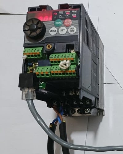
Figure 1. The Mitsubishi FR-D700 inverter. Image used courtesy of the author
Fixed and Multi-Speed Operation
Fixed speed operation is one of the easiest methods to set up. In most VFDs, a preset frequency parameter decides how fast the motor runs when the drive is commanded to Run mode. This setup gives a controlled acceleration and deceleration, protects the motor, and keeps a steady preset speed. No programming is required, but no flexibility is offered.
Fixed Speed Operation
In drives like the Mitsubishi FR-D700, fixed speed operation uses external digital inputs. A run command is sent to the STF (forward run) terminal by connecting it to the common terminal SD via a button or switch. This command causes the inverter to ramp up the motor to a set maximum frequency, and then continue running until the run command is removed. For fixed speed setups, operating frequencies are set through internal parameters, where you can adjust the maximum and base frequency as well as acceleration and deceleration times, as shown in the example table below.
| Parameter | Function |
| Pr.1 | Maximum Frequency |
| Pr.3 | Base Frequency |
| Pr.7 | Acceleration Time |
| Pr.8 | Deceleration Time |
Table 1. The FR-D700 inverter configuration for fixed-speed motor control.
Multi-Speed Selection
Most drives build upon this fixed speed concept by supporting multiple preset frequencies that can be stored and triggered with digital inputs. When a simple switch connects the STF and SD terminals along with the RH terminal, the motor runs at the preset high-speed frequency. Instead of just one fixed speed, the drive can switch between several preset speeds depending on which input terminal is activated. For parameter settings, the high-speed preset uses Pr.4, middle speed uses Pr.5, and low speed uses Pr.6.
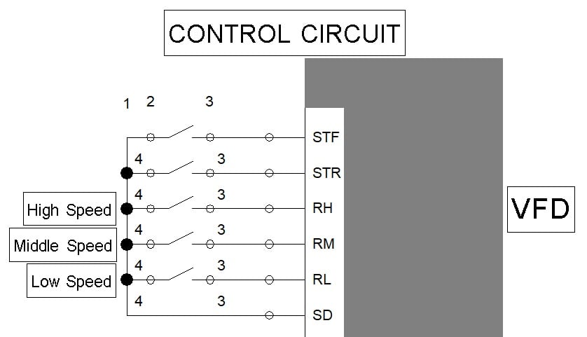
Figure 2. Basic control circuit example for a multi-speed setup: RH is a high-speed input, RM is a middle-speed input, and RL is a low-speed input. Image used courtesy of the author
Besides being easy to set up, fixed and multi-speed VFD control methods offer consistent, predictable operation. This removes the need for extra analog hardware or a communication network.
An obvious drawback is the limited number of selectable speeds, and you cannot adjust the speed gradually or continuously, which makes this method less flexible.
Local Speed Control Using the Drive Keypad
Most VFDs include an onboard keypad that lets operators control motor starting, stopping, and speed directly from the drive using soft key buttons or with the onboard potentiometer. This is useful for commissioning, troubleshooting, or simple standalone machines where you do not need to integrate external control.
On drives like the FR-D700, there is a knob for selecting parameters and a keypad for mode, run, stop, and set. This lets users adjust and run motor speed directly from the drive without an external control system. However, the drive must be set to local mode so the user can enter the desired setpoint and start the motor by pressing the RUN key. While this local control method is quick and straightforward, it is not ideal for automated processes because it relies on a lot of manual input.
External Analog Control Using a Potentiometer
A very common way to control motor speed is by connecting a potentiometer directly to the drive’s analog input. This is a simple and practical way to adjust speed without a PLC or network. The drives reads the incoming signal voltage, usually 0-10 V or sometimes 0-5 V, as a frequency command. Turning the potentiometer changes the voltage, and the drive adjusts the motor speed accordingly.
The potentiometer works as a voltage divider, sending a variable signal to the drive. The drive reads this voltage in real time and adjusts its output frequency, allowing smooth speed control. When the voltage is zero, the VFD runs at minimum frequency (usually 0 Hz), and at 10 V, the VFD runs at maximum frequency. This method offers smooth, continuous speed adjustment and is simple and low-cost. However, the control precision is limited by the knob’s rotation angle, and the signal can be affected by electrical noise and interference.
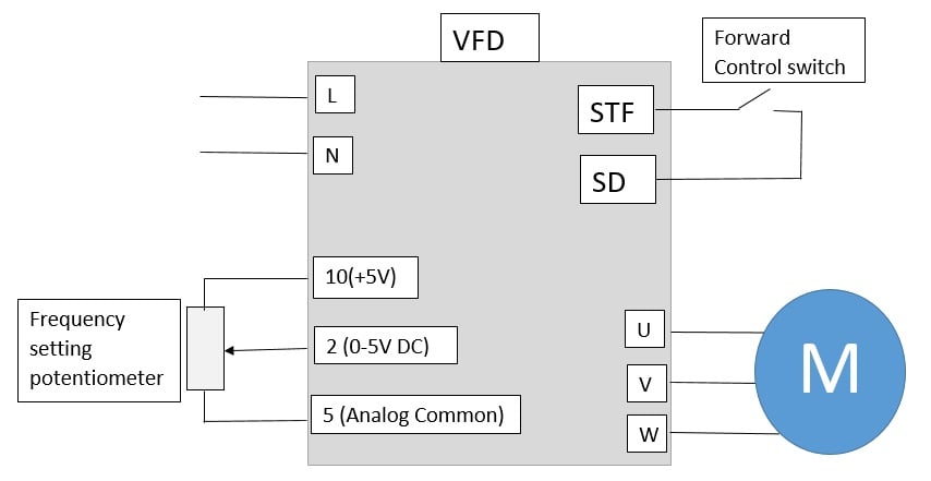
Figure 3. Sketch of the FR-D700 potentiometer connection for frequency adjustment. Image used courtesy of the author
Other devices that provide analog outputs can be substituted in place of the potentiometer. Some VFDs require 0-10 volts, others require 4-20 mA, while some can select between voltage or current sources.
Network Control via Serial Communication
Serial communication networks, like RS-232 and RS-485, allow PLCs and HMIs to send digital commands directly to the drive using protocols such as Modbus RTU. In many networked systems, RS-485 is used because it resists noise and can support several devices on one network. Commands are sent to specific registers in the drive to perform tasks like starting and stopping the motor, setting the target frequency, and getting status or fault codes. The drive interprets these commands and adjusts its output as needed.
Here, the PLC acts as the master and the VFDs are slave devices, each with a different station number for targeted commands. This control method is precise, reduces wiring complexity, allows one controller to manage several devices, and gives access to drive diagnostics.
Networking does require more configuration than simple I/O signals. Setting it up requires careful attention to parameters like baud rate, parity, and station address, so technicians need a solid understanding of communication protocols.
Network Control via Industrial Fieldbus
Most modern VFDs can connect to industrial Ethernet networks, allowing centralized speed control and monitoring as part of a larger automation system. Unlike analog and serial control, Ethernet-based fieldbus protocols support fast, two-way data exchange between drives, PLCs, and supervisory systems.
Examples of these networks include PROFINET, EtherCAT, Ethernet/IP, and Modbus TCP. With the right communication module, drives like the FR-D700 can work as network nodes with a DCS system. The PLC sends data packets over the Industrial Ethernet network to command the drive, either on a schedule or polled as needed. The drive then adjusts its output and reports back real-time feedback, such as load current, actual speed, or fault status. This setup is great for managing multiple drives over large systems.
The main drawback is that, like RS-485, networking is more complex to configure than basic analog or serial wiring and the hardware costs are usually higher.
Choosing the Right VFD Control Method
Each VFD speed control method offers a different mix of simplicity and features. The best choice depends not on the drive model, but on how you want the motor to work in your system. For basic uses, simple options like fixed speed, preset multi-speed input, or a local potentiometer are practical.
As systems get more complex and need synchronized control, options like PLC-driven analog signals or serial communications become more useful. For large-scale setups, industrial Ethernet networks provide the most advanced control, but they require more setup time and investment. Choosing the right method helps make sure your system is effective and well-suited for its purpose.
Featured image used courtesy of Adobe Stock
Looking for more info about motors and motor controls? Have a look at this handy wiring infographic and other links below.
Articles:
- Comparing Single-Phase and Three-Phase Motors
- 3-phase Motor Types: Synchronous and Induction Motors
- Understanding Delta Wound Motors for Industrial Applications
- Brushed vs. Brushless DC Motors
- Field-oriented Control (Vector Control) for Brushless DC Motors
- Teardown: What’s Inside a 3-Phase Induction Motor?
Textbook:
Related Content