Facebook
 Google
 GitHub
 Linkedin
How To: Use the Arduino PLC IDE to Build Basic Ladder Diagrams
Following the release of the official Arduino PLC IDE, this tutorial will introduce programming and understanding of the function blocks common to all IEC 61131 languages, starting with bit commands, timers, and counters.
The Arduino microcontroller system now includes a professional series designed to implement industrial machine control functions. These platforms support industrial voltages, and now, industrial programming languages.
At the time of writing, the only hardware platform on which the new PLC IDE can be used is the Portenta Machine Control (abbreviated PMC hereafter). Since that time, at least the Arduino Opta platform has been added to the compatibility list.
Where Do I Start?
It is recommended before following this guide to ensure that your PMC and software are both successfully installed and the initial configuration program downloaded. The guide for this procedure can be found on the Arduino website.
Getting the PMC configured with a proper license and first program is a critical step, so the following guide assumes you have a functional PMC ready for its first hardware and ladder logic program.
Installing I/O Devices
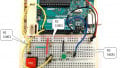
For this first set of sample programs, only digital inputs and outputs will be required. This tutorial will include two digital inputs and two digital outputs.
-
Input: A selector switch will be connected to Input 01, which has the address of %IX0.1 in the IDE
-
Input: A pushbutton will be connected to Programmable I/O 00, with the address of %MX3.0
-
Output: A 24 VDC relay will be connected to Output 00, with the address of %QX0.0
-
Output: A second 24 VDC relay will be connected to Programmable I/O 03, with the address of %MX3.3
These choices of devices and addresses will serve to illustrate the dedicated and programmable I/O in the software setup.
The digital input bank must be connected to ground, and the output bank connected to +24 V. The programmable bank must be connected to both +24 V and ground.
Configuring the Tags
First, we must correlate the I/O addresses with logical names. For this step, the IDE provides a ‘Local IO Mapping’ menu from the ‘Resources’ tab on the left side of the screen.

Figure 1. Resources window with IO maps.
Here, the Inputs, Outputs, and Programmable I/O can be matched with a descriptive name that will be used in the ladder program.
First, I open the Digital Inputs menu, find the address corresponding to the input terminal 01, (%IX0.1) and give it the name SS1, for Selector Switch 1.

Figure 2. Digital Inputs mapping menu.
Next, I do the same with the Digital Outputs menu, labeling terminal %QX0.0 as ‘Relay1’.
Finally, I chose to use two of the Programmable Digital I/O terminals simply for the sake of demonstration. These two terminals, (%MX3.0 and %MX3.3), correspond to the real-world devices pushbutton 1 (PB1) and Relay2.
Since MX3.0 is an input, it must be selected as such. MX3.3 is an output, and must also be selected, as shown in the diagram below.

Figure 3. Programmable IO mapping menu.
This input/output selection process is akin to using the pinMode function in the Arduino text IDE.
Basic Ladder Program
In the ‘Project’ tab, a default main program is created. To demonstrate Ladder Diagram programming, go up the Project menu -> New object -> New program. Provide it with a name and be sure to select Ladder Diagram (LD).
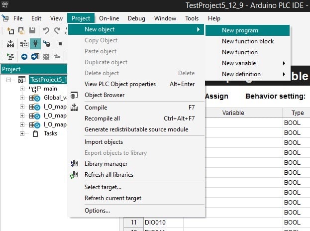
Figure 4. Creating a new Ladder Diagram (LD) program.
Note: If the ‘New program’ sub-menu is grayed out, click to select the top parent of the project tree on the left Project window.
With a new LD, the default main ST program can be deleted.
The LD program opens with a default single NO contact and single momentary output coil.

Figure 5. New Ladder Diagram (LD) default view.
There are several options at this point:
- Right-click on the rung number to be presented with additional rung insertion options.
- Right-click on the input contact to place other contacts in series or parallel configuration.
- Right-click the coil to place another coil in series.
The following image illustrates each of these menus, from left to right.

Figure 6. Left to right: new network menu, contact menu, and coil menu.
Double-click on the NO contact. Either type the name of the label you gave to the input (SS1 in our case) or press the three dot button (...) to open the entire variable (tag) listing. You can choose from there.
Repeat the same process for the output coil Relay1.
Download the program, which you should have accomplished once already in the initial setup tutorial. It can be found near the upper-left corner and in the menus.

Figure 7. Two ways to download the code to a connected controller.
Test the Programmable I/O Terminals
Add a new rung, also called a ‘network’, below the first one. Use the single NO contact PB1 and the output coil Relay2.

Figure 8. Two networks using Digital and Programmable I/O.
With this program built and downloaded, the selector switch and pushbutton should each energize a single relay.
Simple Timer (TON)
A long list of familiar function blocks can be found in the Library Tree near the right side of the page. Find and drag a TON onto your ladder rung in place of SS1. Call it Relay_Timer.

Figure 9. Adding a TON to a program.
We will continue to use SS1, but this time we will delay for 3 seconds before energizing Relay1.
When you provided the name ‘Relay_Timer’, the IDE automatically created a new tag of data type TON containing the following elements: IN, PT, Q, and ET.

Figure 10. The TON with variable view.
IN, the control input, will be activated by SS1.
PT is the preset time, and it can either be a constant value or it can be its own variable tag. In this example, we will use a constant value of 3000.
The Q output will energize when the timing cycle is complete (since this is a TON).
The ET variable is the current value of the timing cycle as it progresses. This is an unsigned double integer (UDINT).
I have created a new variable called ElapsedTime, with the data type UDINT to store the current elapsed time value.

Figure 11. Complete 3-second TON command, ready to download.
Using these controls in the rung, download the program and energize the selector switch. A brief, three-second pause should occur and then the relay should energize.
Simple Counter (CTU)
The counter is very similar to the timer, except we must have a manual reset option for the counter.
Delete the Timer and replace it with a CTU function block. This will look very similar to the timer, but it includes an ‘R’ input, for the reset.
For this reset, use PB1. For the PV (preset value) use a constant value of 5, and for the CV (current value) create a new UDINT with a name of CurrentVal.

Figure 12. Complete CTU instruction, ready to download.
-- As a side note, you can simply click and drag variable names down to the function block and drop them in appropriate places.
When downloaded, repetitive energizing of the selector switch should cause the relay to energize after the 5th switch action. If the pushbutton is pressed at any time, the counter value will reset to zero.
Advanced Commands
The Arduino PLC IDE is equipped with far more function blocks and advanced capabilities, including the use of EDS files to add manufacturer-defined hardware items on a network. These functions will be covered in future articles.
If you have an Arduino, but perhaps not the Portenta Machine Control, yet are still interested in learning new PLC functions, there are a few other options available to learn and explore.
Want to test your knowledge of PLCs? You think you N.O. a lot about ladder logic? Are you a normally-open or normally-closed minded engineer?
Check out our PLC Programming worksheet!