Facebook
 Google
 GitHub
 Linkedin
Handling of Power System Data | Indications, Counters, and Data Flags
For large process systems, learn how the location of data indication and flag processing can increase or decrease the burden on computers at the device, RTU, or main computer level.
Within power control systems, local data acquisition and analytical functions are employed to reduce the processing load at the control device and main computer levels. The data processing functions have been deployed at different acquisition levels to efficiently handle and treat the primary data, including indications, control, counters, and data flags for data quality and accuracy.
Detecting State Changes for Indications
All indications are monitored for state changes, and the change detection process or function is initiated at the application level. In short, the indications are contact closures which are detected at the digital input (DI) board.
The two basic indication types are supported: single and double. Single indications involve only a single monitored external point and have only two states: 0 or 1. Double indications involve the monitoring of two physical external points (the open and the closed auxiliary contacts of a breaker, for instance). When processed, these indication points are defined to the RTU as a pair and represent 4 unique conditions (1/0; 1/1; 0/1; 0/0). The 1/1 and 0/0 states reflect an intermediate or transitional state of the monitored device.
Let's talk about the RTU-specific indication detection scenario. The indications are received from the RTU in blocks and only those blocks are transmitted to the system from the RTU which pertain to at least one state change as detected by a DI in the RTU.
The event processing is initiated when a state change is detected. The state change detection is for each telemetered, whether single or double indication, by comparing the received indication state with its state in the database. The current updated state is then stored in the database.

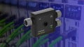
Figure 1. Control devices, like valves, register as process indicators. Image used courtesy of Adobe Stock
Time Supervision of Double Indications
Double indications which reflect the transition state (0/0 or 1/1) are subjected to time supervision to ensure that the condition is truly transitional and not a device anomaly.
A long delay will initiate event processing. The allowable transition time can be defined for each type of process device i.e. breaker, isolator, inlet valve closing/opening, etc. For this purpose, every double indication is assigned to a delay group corresponding to the type of device.
Counter Processing and Supervision for Energy Calculation
The pulses relate to a certain value, generally energy, and this pulse count is connected to a digital input on an RTU accumulating the pulses. Those pulse counter values are transmitted to the master station. The pulses are read at regular intervals on the digital input boards, then at the end of each sample period, all the pulse count values in the RTU are read. The pulse counter values are time-stamped and transmitted to a master station which stores them in a database. The pulse inputs that are blocked for pulse counter values are not scanned or sent to the master station.
The RTU stores only the number of pulses in its database. The master station scales the pulse counter values and stores them in its database for internal use. Then the process-related values like energy are obtained by multiplying the number of pulses with the value represented by each pulse, often called “value per pulse.”
The counter may either be cleared at the end of the period reading e.g. once each hour, or perhaps never as long as the device is not restarted. For supervision, a check is performed to determine that the previously stored values have been transferred before a new reading is stored in the database. In the event of an error condition e.g. faulty input board, the counter values are marked as invalid before transmission to the master station.
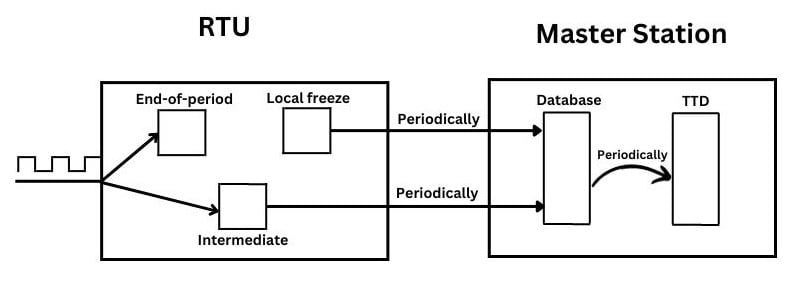
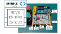
Figure 2. Acquisition of energy pulse counters from RTU to server
Blocking and Unblocking Functions
The blocking functions are used to stop specific types of processing of data like blocking of the data acquisition, processing of alarms, control of power system devices, the execution of calculations, and printout of reports. The system supports blocking and unblocking functions for the measurement, indications, control, and report printout. Similarly, the block alarm processing function is used to inhibit the processing of alarms for individual telemetry data. This function prevents the alarm list and the alarm status of the object from being updated when subsequent alarms occur for the object.
The control block function is the most crucial function that is used to prevent subsequent supervisory control dialogues from actually controlling a device. In the real world, an example of a control block is to block the open/close command from the operator console for the circuit breaker and isolator while the maintenance crew is working on the equipment.
Common Data Flags for Measurement, Indication, Control and Counters
Data flags are associated with measurements, indications, and pulse counter values, and they are used to identify the conditions and quality of the data. The numerous flags are set automatically due to the processing of acquired data (remotely or locally) by the data processing functions. Other flags can be set explicitly with the manual data entry dialog by the operator. A common control system architecture supports the following main common data flags:
Manually Entered Data Flag
This flag is set for a measurement, indication, or pulse counter value whose value has been manually entered by the operator with the manual data entry dialog. This flag is not set for non-telemetered objects.
Data Acquisition Block Flag
This flag is also set for a measurement, indication, or pulse counter value with the manual data entry dialog wizard. For measurements and indications, the flag may also be set automatically when manual data entry is performed for the corresponding value.

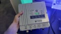
Figure 3. Power plants rely on data acquisition to determine operational output. Image used courtesy of Adobe Stock
Updated Data Flag
It is reset by the data processing function for a measurement, indication, or pulse counter value that is not being acquired due to a telecommunication problem or a device problem, or an invalid due to an A/D drift limit violation. When a normal data entry is performed for the corresponding value, the flag is automatically set to Updated.
Alarm Block Flag
This flag is set for a measurement or indication with the manual data entry dialog.
Control Block Flag
The flag is set for a controllable power system device or objects like breakers, and isolators with the manual data entry dialog.
Handling Power Data to Optimize Workload
The handling and processing of power system data of indications, controls, and miscellaneous flags in control systems are requisite for the operation and control of the power generation and transmission infrastructure by relieving the extra processing load on control devices and main computers.