Facebook
 Google
 GitHub
 Linkedin
Handling of Power System Data: Engineering Limits and Data Currency
Power systems rely on meaningful data, as do most other processes. Within SCADA environments, individual data points are tracked, compared to limits, and evaluated to obtain current readings.
Data processing is a popular buzzword used in the data acquisition field, referring to the handling of the power system data in the application server. The data can be acquired locally or remotely, manually entered, or produced by another application. In a nutshell, the processing and handling of the data from the power system to prepare it for use by the operator and the power application programs.
Methods Used in Data Processing
The methods behind data processing and handling deal with the following types of data items:
- Measurand Values
The measured value inputs are received at the analog input card level of the PLC or RTU, sampled at a defined frequency and then stored internally in binary form. The measured values, after A/D conversion, are stored as engineering units and checked against limits, including zero-range processing.
- Indications
The indications are monitored for state changes which are detected by comparing the received state with predefined values in the database. The system handles single indications as well as double indications.
- Counters
The energy values in power systems are supported using counters. The pulse counter values are accumulated in the RTU and are periodically transmitted to the central system. The values are time-stamped and converted to engineering units in the application server.
- Data Flags
The data flags are common to all power system data, used to identify certain data conditions. They can be set automatically by process events or by manual data entry.

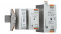
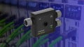
Figure 1. Small RTU unit to get data from I/O devices to a SCADA system. Image used courtesy of Define Instruments
Measured Value Processing
Every telemetry measured value acquired from a field transducer or from a calculated or manually entered value must be processed at the server level before being stored in the system's central primary database. The processing includes conversion to engineering value, limiting checking, zero range processing, etc., which will be discussed briefly in this article.
Conversion of Engineering Units
For analog-type values, the primary information is converted to proportional DC current or DC voltage in a measured value converter. The binary representation is converted to engineering units (kV, MW, MVAr, psi, etc.) using either a linear conversion (y = mx + b) or a nonlinear conversion algorithm.
Local and Remote Limit Checking and Violation
Operating limits are used to delineate the nominal operating ranges for associated measured values. The term measured value means acquired value, calculated value, and manually entered values. Each value may be assigned up to two pairs of limits. Typically two limit pairs are used to identify the warning conditions and emergency or alarming conditions for the value being monitored. Event processing is initiated at the master station when a limit violation is detected. The limit checking may be implemented at either the RTU or at the master station. It is possible to max both local and remote limit checking.
The detection of limit violation results in an appropriate status flag for the object being updated about a particular limit (warning limit and alarm limit) that was exceeded. The measured value is stored in the data repository, and event/alarm processing is initiated for all detected limit violations according to alarm processing.
Deadband Processing, or Hysteresis
The deadband processing function is usually employed within control systems to manage events efficiently. The deadband processing in the context of event handling is used to reduce events or alarm generation in the system, hence improving the overall control system performance, particularly in tripping situations where thousands of events/alarms are generated which will overburden the control system.
To eliminate needless multiple alarm generation for values fluctuating around a defined operating limit, each measured value for which operating limits have been defined can be assigned a non-zero deadband known as a hysteresis gap. A limit violation is detected for a measured value as soon as the limit value is crossed. However, to return to normal, the measured value must cross the limit value in the return-to-normal direction by an amount that exceeds the deadband value for that measured value.
After defining the alarm and warning limits for any signal, some specified value defines how large the hysteresis shall be around the warning and alarm limits, as shown in Figure 2. As already described, hysteresis (deadband) reduces the number of events in the system when real values oscillate around the limit. The system event log combines unacknowledged alarms, any audible alarm, any update of the event list, and a print output log.

Figure 2. Upper alarm limit and upper warning limit deadbands
The Deadband for Zero Value, or ‘Zero Range’ Processing
The zero deadband is the area in which the measured value is considered as zero (0). The zero range processing is utilized to provide a definite value when a value is close to zero. This process uses a deadband to create a null zone around zero and is definable for each telemetered value. The measured values within the zero zone are shown as zero to the operator on the screen with the yellow color. For example, if the zero deadband is 3 A, the values from -3 A to +3 A are still considered to be 0 A.
Stale Data Monitoring for Measure Values
The plant control systems are used to continuously monitor and control the different industrial processes and real-time data is traditionally collected from field devices and sensors. The ‘stale data’ phenomenon means when there is a delay or lost update in process value, this means this data no longer reflects the current state of the equipment or system. The invalid or non-updated data is shown in a different color on the screen of the operator workstations.
The stale data monitoring application supervises selected measured values like volts, ohms, etc. for staleness. If a value is detected as ‘stale,’ the measured value is marked as such and set as ‘not updated’ or ‘invalid’ in the database. An event or alarm will be generated.
When a new update is received, the ‘stale’ marking is removed from the process value and the measured value is set to current. The criterion for ‘stale data’ is that a value has not been updated with a value that differs more than a configurable deadband during a configurable monitoring period.

Figure 3. Control panels, regardless of generation, should display data logically, with clear alarm and safety limits. Image used courtesy of Adobe Stock
The following conditions exclude the measured from monitoring:
- The measured is marked ‘not updated’ by some other reason than stale.
- The measured value is manually entered.
- The measured is in zero zones provided that zero zone supervision has been specified for the measured in question.
- The operator has manually excluded the measured from stale data monitoring.
Summary of Data Processing
The handling of process data related to the power system is vital for maintaining the reliability of the system. The measured data includes information about voltage, current, pressure, level, and other parameters collected from various sensors and gauges and the proper handling of this data includes zero-zone processing, deadband, limit checking, and stale data monitoring.
Featured image used courtesy of Canva