Facebook
 Google
 GitHub
 Linkedin
Setting up Discrete Sensors: Polarity, Mode, Range, and Limits
Installing sensors into a manufacturing process is intended to collect data, useful in making logical true/false decisions. But what settings must be adjusted when you install these sensors?
There are two kinds of sensors in process manufacturing: those that provide on/off signal outputs, called ‘discrete’ sensors, and those that provide a finite signal to display the current sensor value, called ‘analog’.
Sometimes, these values are provided over an industry-standard protocol, like Modbus or IO-Link, but when they are processed by the PLC, they will appear as a value that takes on a binary number of 1 or 0, or it might be an integer between 0 and a larger upper limit.
For analog sensors, the programmer has a lot of power. He or she can use the value to provide high and low process values, like a limit switch, or extreme alarm values. This is quite useful, but it often requires specialized input modules and a knowledge of voltage and current engineering values.
For many simpler systems, the discrete sensors are used to provide a basic binary switching action, requiring absolutely no programming input from the programmer except the detection of a boolean value (sometimes in the form of an XIO or XIC contact). Although this might sound easy, there are a few settings that must be considered in order to build an effective system.
For most sensors, these settings include the polarity of the output signal, the sensing mode, the range, and to expand on the range, there may be extended limit values.
Sensor Signal Polarity
There is much talk on the internet about the NPN or PNP polarity of a signal, but it is absolutely critical to building a functioning system. Unfortunately, this is not a parameter that can be toggled by a simple switch, since it uses a combination of internal transistors. There are three different kinds of sensors in this group.

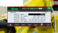
Figure 1. This sensor is provided with exclusively a PNP (sourcing) output only. Image used courtesy of SICK
Exclusively PNP or NPN Sensors
These sensors have a rating in the datasheet - they can only be PNP or NPN, and nothing can change the output. If they are connected to the wrong system, no damage will occur, but the signal will not be received.
PNP/NPN sensors with Separate Outputs
For some sensors, there are two output wires. Most commonly, these would be the black and white wires coming from the normal M12 QD cable system. But be careful; just because the white wire is used, it has many different purposes. Not all sensors can provide both an NPN and a PNP signal option.
PNP/NPN Software Configurable
This polarity switch is normally only made possible in the modern world of IO-Link sensors. Just as a PLC input module can be made to switch between sourcing and sinking via the software, some sensors can also be made to toggle between PNP and NPN with a software command.
NO/NC Mode
The next setting is a bit more flexible in the electrical sense. Any discrete sensor has a small amplifier chip inside. When the measured quantity (perhaps light, or ultrasonic distance measurement) exceeds a threshold, it can either provide an ON or an OFF signal.
This differs from the previous polarity setting, although they sound similar.
When a sensor is set up to be PNP and normally open, the output will be +24 v if ON and a closed switch if OFF. If normally closed, the output will be a closed switch if ON and +24 v if OFF. This means that electricity will flow from the sensor to the module when the sensor is energized.
On the other hand, if a sensor is set up to be NPN and it’s normally open, the output will be 0 v if ON and a closed switch if OFF. If normally closed, the output will be a closed switch if ON and 0 v if OFF. This means that electricity will flow to the switch, NOT to the module, when the sensor is on.

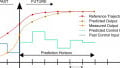
Figure 2. The image and matching wiring diagram for an optical sensor with both an NO and NC output on one PNP sensor. Image used courtesy of AutomationDirect
This all means that the polarity (NPN or PNP) is non-negotiable. The sensor and module must work in harmony with each other. However, the NO/NC mode can be toggled to provide a high or low output depending on the needs of the system.
For optical sensors, this NO/NC toggle might also be labled as ‘light on’ and ‘dark on’.
Sensor Range
This parameter is what causes the sensor to act a bit like a limit switch. When a certain threshold is reached, the output will energize, but can you choose this threshold? And if so, how?
In some cases, you cannot. The sensor has no adjustment, so you must simply move it closer to the sensed object. This is the case for many optical sensors and inductive proximity sensors.
However, a number of sensors are on the market that allow adjustment options, and more are appearing constantly.
The primary traditional method of adjustment is a potentiometer, which changes the sensor's sensitivity when comparing the real-world input to the measured set point. Simply turning the small potentiometer will adjust the range of the sensor for a particular product. In many other cases, a small rubber tactile button can enter and exit the teaching mode.

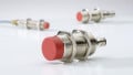
Figure 3. In this sensor, a small tactile push-button can teach the set limit position. Image used courtesy of Banner Engineering
The only problem with the manual adjustment is that it must be performed while the sensor is installed. It may be difficult to access, or touching the sensor might knock it out of alignment. For this reason, many engineers prefer software adjustments. Sending a short series of pulses to one of the signal wires can enter and exit the teaching mode, just like the button. In the case of IO-Link, adjustment parameters can be transferred to the sensor on startup to accelerate the teach process for a brand-new sensor.
Limit Values
Limit values are usually only present on discrete sensors with a communication protocol. When only one signal wire is present, that wire can go high or low, providing only one set point. Many new sensors, again, particularly of the IO-Link variety, can be fitted with two discrete signal limits, so they may act as both high-level and low-level sensors, while only requiring one physical device.
Sensor Configuration
It can be difficult to know exactly which sensor to use in every setting, and far more difficult to know how to set them up. But rest assured, a thorough study of the datasheet can provide all the info you need to know and it can assist you on your journey to successful control system operation.