 Facebook
 Google
 GitHub
 Linkedin
Programming B&R PLCs With Automation Studio
While B&R PLC controllers are quite different from typical PLCs, Automation Studio offers tools and features that make programming them less intensive. In this article, we’ll discuss how to program B&R PLCs with Automation Studio.
Every PLC or automation controller has its own programming software. This software allows technicians and controls engineers to develop custom programs that interface with field components and troubleshoot those programs. Some software is completely integrated with motion control and HMI development, while other software focuses on just the automation component of the project.
Some automation programming software uses the IEC 61131 standard which offers five standard programming languages: ladder diagram, instruction list, function block diagram, structured text, and sequential function chart. Below I’ll give an overview of how to use Automation Studio along with some tips that might make your next B&R project go a little bit smoother.
Figure 1. Automation Studio’s automation code is all contained inside of one software. Image used courtesy of B&R
Automation Studio
Automation Studio is a fully integrated programming software, which means that the automation code, HMI, simulation, diagnostics, and hardware configuration are all contained inside of one software. The software is broken into three sections: the physical view, the configuration view, and the logical view. Each project can have multiple configurations and physical layouts, but they will all share the same logical view. This is beneficial for OEMs where they might have multiple versions of the same machine but with different hardware.

Figure 2. Automation Studio’s physical view provides a graphical representation of your project with all of the physical components laid out in one place.
The Physical View
This is where you lay out all the physical components within your system. Automation Studio uses this view to determine addressing within the network, if applicable, and provides a graphical representation of your project. B&R uses PowerLink network topology for its Ethernet protocol. The PowerLink network makes use of node addressing and can automatically address components on the network.
In the physical view, the designer must lay out the network as it will be laid out in the field so that the system can address components accurately. Devices can be dragged into the program workspace from the toolbox and connections can be made by clicking on the ports of each device and dragging the connection line to the next device. Node addresses can be selected manually or by the order in which devices are added to the system. Right-clicking on most components will open a configuration screen where you can change default properties.

Figure 3. Automation Studio’s configuration view is used to look at configuration details, which are added from your toolbox.
The Configuration View
Once the physical view is set up, you can start defining your configuration. Major features require configuration files to be added from the toolbox. By highlighting different components within your configuration view, you will have different options in the toolbox. For example, if you would like to add a recipe management feature, you will need to click on the mappRecipe folder and then open the toolbox and add the corresponding configuration file by clicking and dragging the file into your mappRecipe folder. If you have servos or an ACOPOSTrak in your project, you will need to add those configuration files to the mappMotion folder. Once the configuration files have been added, you can then change the configuration as needed. Multiple configuration views can be added to facilitate different machine configurations.

Figure 4. Automation Studio’s logical view is where you can find your field device codes.
The Logical View
This is where the code that controls your field devices for your project resides. Automation Studio is IEC 61131 compliant so you have access to ladder logic, structured text, and function block diagram programming languages, and, with B&R being PC-based control, you also have access to C++. While these languages are all available to the user, the structured text is my preferred language when using PC-based control systems. Not only do you program your machine or process in the logical view, but also your HMI programming is done within the logical view under the mappView folder.

Figure 5. Automation Studio’s program structure is similar to structured text. Image used courtesy of Unsplash
Variables, Programs, and Action Files
The program structure is similar to other structured text programming interfaces. There are programs and subroutines that can be called throughout the program. In Automation Studio, these subroutines are referred to as action files. Variables and custom types or structures are defined in exterior files and can be locally scoped or globally scoped. Every program will have an initialize, cycle, and exit action. The initialize and exit actions are called automatically when the CPU starts or has been issued a stop, otherwise known as first scan and last scan.
Function Block Library
Automation Studio comes pre-installed with a vast library of function blocks. These function blocks are used for controlling B&R equipment or using features of the B&R controller such as recipe management or writing text files. To add function blocks to the library, simply click on the library folder and open the toolbox. Within the toolbox double click on the green library icon. This opens a wizard that allows you to select multiple library files which contain the necessary function blocks.
Program Structure
Now that we have a general understanding of how Automation Studio works, we can start to develop our project. The first step is to build the hardware view and add any necessary configuration files that your project might need. When laying out the code for the project, try to break up your project into multiple sections. If we are programming a machine, create folders for each cell and station then a program for each sequence of events. For process control applications, try to separate each process in the same fashion. By compartmentalizing your code, you make troubleshooting easier as the code structure expands.

Figure 6. Using a state machine in Automation Studio to add a sequence to an application makes for easy-to-read sequences.
Sequencing In Structured Text
With ladder logic, there are multiple ways to add a sequence to an application, but with structured text, it is a little bit harder. B&R offers many types of sequencers within the Automation Studio program, but I prefer to use a state machine. A state machine is really just a case statement that uses a special data type called an enum. An enum is a data type that allows you to set predefined string constants, so when we inspect a variable with a type enum in a case statement, we can compare names instead of numbers. This makes for easy-to-read sequences. Within each state or sequence step, there would normally be conditions to set the next state. Each state change requires one full scan of all the code which ensures outputs are being set and inputs are being read on each scan.
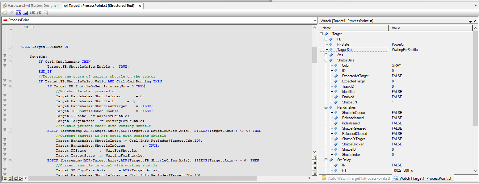
Figure 7. The built-in simulator can be used to debug your code.
Troubleshooting / Debugging
Once all of your code is developed, you can start to debug using the built-in simulator by clicking on the traffic light in the toolbar. You can switch into monitor mode once the controller is online by clicking on the magnifying glass in the toolbar—an auto watch and watch window will pop up. Using the watch window, you can add variables by right-clicking on the watch window or by clicking and dragging them into the watch window. This is a powerful tool that allows you to monitor the live values of variables. You can also override variables that are not being set in the code.
Another debugging tool is the trace window, which can be opened by right-clicking on any program within your project. The trace window allows you to trace variable values continuously. The maximum size of the trace is set using the trace properties and the values will be overwritten as the maximum size is reached. After the trace is stopped and the data is displayed you can change the time window of the graph and view the variable value at each CPU scan.
Less Intensive Programming
While the B&R PLC controllers are quite different from typical PLCs, Automation Studio offers many tools and features that make programming less intensive. By using the organizing and debugging tools within Automation Studio and the simulator function, much of the project can be debugged before the equipment even hits the floor. These features can save you time and money when developing a control project.
Related Content


> being PC-based control, you also have access to C++
What makes it PC based? AR Embedded is VxWorks based, like a majority of other brands (including AB Logix). B&R’s hardware architecture varies, but includes traditional DIN mount boxes, not just Industrial PC. The DIN mount varieties do C and C++ too.
They do have ARwin runtime options that run along side Windows (not unlike CompactLogix 5480). Would you call Allen-Bradley “PC Based”?
I see “PC Based”, “SoftPLC”, and “Soft Real-Time” used to take subtle jabs at tech forward brands like B&R and Beckhoff, like they aren’t “real” PLCs. What I rarely see are technical definitions of the terms and/or justification as to why they apply to some product lines or brands and not others.