 Facebook
 Google
 GitHub
 Linkedin
State Machine Programming in Ladder Logic
This article discusses the concept of state machines and state machine programming, particularly when utilized with ladder logic.
Overview
Ladder logic is a common visual programming language that can execute in a PLC. Ladder logic is used to control machinery and direct processes in industrial control applications.
Frequently, there is a desire to utilize ladder logic for sequential control applications. Sequential control produces process outputs that not only depend upon the state of process inputs but also based on the history of the input patterns. Representing sequential control via the concept of “state machines” is an established and appropriate technique.
An example where sequential control might be applicable is in the control of a traffic light. The traffic light change may be triggered by a particular flow of traffic that has occurred in the recent past. We examine a simple sequential control example of a basic conveyor and demonstrate the methodology involved in defining the problem in terms of states.
The state description is then manually translated directly into ladder logic. A nice property of this methodology is that “if then else” rules along with the ability to perform “looping” can be applied to ladder logic.
The Development Process Methodology
State Module Definition
Each distinct segment of sequential control is represented by a module. A module includes the functional description of the behavior of a self-contained “chunk” of sequential logic. The modules are defined naturally by partitioning the control application.
Commonly, a module represents the function of a single piece of equipment such as a pump, valve, fan, tank, mixer, blower, etc. The behavior of each module is defined based upon an understanding of the process and specific equipment such as actuators and sensors on the plant floor.
As a simple example, consider the conveying system depicted in Figure 1 below. The operator places a load at the far right end of the conveyor and pushes the “start” button. The load is then conveyed to the left end of the conveyor, and the conveyor stops when the photoeye is blocked by the load.
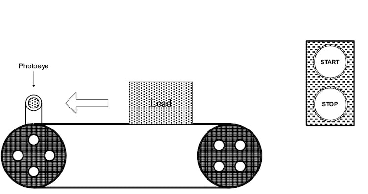
Figure 1. A conveyor system example is explained above.
The conveyor then waits for an external command originating from another module. When the command is received, the load is transferred off the conveyor, and the conveyor stops once the load has cleared the photoeye. After the operator has pushed the “start” button but, before the photoeye is blocked, the operator has the option of pushing the “stop” button, causing the conveyor to halt. The operator may subsequently restart the conveyor sequence by pressing the “start” button again.
In this example, a single fault condition is implemented. If the conveyor is running and the load fails to reach the photoeye within a prescribed period of time (10 seconds), a fault is detected, and the conveyor stops.
After correcting the problem, the operator is required to reset the conveyor by clearing the fault through the man-machine interface. Following the reset, the operator may subsequently restart the conveyor sequence by pressing the “start” button.
Module Documentation
For each module, a state transition diagram is created. The diagram can be hand-drawn, or preferably a software drawing tool can be used to generate the diagrams. The state transition diagram for the conveyor example is illustrated in figure 2 below.
The boxes represent states, whereas the arcs between the states represent events that define the set of transitions between states. The states and events are identified by both a short description and a number. In our example, the conveyor is initially in the “Idle” state (by convention, the first state, S1 is considered to be the initial state).
When the operator presses the “Start” button on the control panel, the transition “Start” (event E1) is taken, and the module transitions to the “Running” state (state S2). While in the “Running” state, the conveyor motor is energized. Each event is triggered by a set of predefined conditions. For example, “Start” (event E1) is triggered by pushing the start push-button.
Typical event conditions are:
- Internal to the module (e.g., a timer started by this module has expired)
- External to the module (e.g., a “command” variable, telling this module to “do something,” was set by another module)
- External to the controller (e.g., a push-button input goes true)
Typical state actions are:
- Internal to the module (e.g., run a timer)
- External to the module (e.g., set a “command” variable of another module, telling another module to “do something”)
- External to the module and sent to the controller (e.g., turn on a motor)
State actions may either be “continuous” or “one-shot.” Continuous actions, such as running a timer, need to persist while in the state. One-shot actions, such as latching an output, or incrementing a counter, need only occur once when transitioning into the state (edge versus level triggering).
Additional documentation defining both the event conditions and the state actions should also be provided. Listing 1 shows the accompanying documentation for the conveyor module.

Figure 2. The CV1 State Transition Diagram.
CONVEYOR CV 1
EVENTS
CV1_E1
Start
- Set when:
The “start” push-button is pressed.
CV1_E2
Stop
- Set when:
The “stop” push-button is pressed.
CV1_E3
Load Positioned
- Set when:
The photoeye is blocked (input = 1).
CV1_E4
Position Time-out
- Set when:
The position fault timer has expired
CV1_E5
Reset
- Set when:
The MMI sends the “reset” command (unlatch upon receipt).
CV1_E6
Eject Load
- Set when:
The “eject load” command is sent (unlatch upon receipt).
CV1_E7
Load Ejected
- Set when:
The photoeye is clear (input = 0)
STATE PROCESSING
CV1_S1
Idle
Do:
- Stop the conveyor motor (one-shot).
- Unlatch the “position time-out” fault event (one-shot).
CV1_S2
Running
Do:
- Start the conveyor motor (one-shot).
- Run the position fault timer (continuous).
CV1_S3
Position Fault
Do:
- Stop the conveyor motor (one-shot).
CV1_S4
Load Positioned
Do:
- Stop the conveyor motor (one-shot)
CV1_S5
Unloading
Do:
- Start the conveyor motor (one-shot).
Listing 1. State machine module documentation.
This article should provide you with some initial steps needed to understand state machine programming in ladder logic. Another article will dive deeper into module implementation, and the potential for advanced users to construct software tools capable of generating the appropriate ladder logic from a high-level state language description.


Ladder logic is a poor tool for implementing state machines. Obviously it can be done but SFC or sequential function charts are much better. In each step one can use ladder ( LD ) or structured text ( ST ). I prefer structured text. On top of that, a good SFC implementation will high light the current active steps. Better yet is to log the transitions from one step to another.
Enjoyed your article…I try to promote state machine plc programming in my plc classes…i have found that using asm charts seems to be helpful . I try to show that a state machine properly documented by a graphical method or chart can then be implemented in whatever you prefer . Ladder, SFC, Structured Txt, or we even do a ardunio implementation at times.