Facebook
 Google
 GitHub
 Linkedin
Obtaining System Values in a PLC
It’s easy to obtain I/O values for local and remote modules and network nodes. But what about system data that’s built into the PLC? How can we access and use that information?
A PLC is just like a computer in many ways. Perhaps the most obvious is how it’s used differently according to who’s in the driver’s seat.
For some people, the simple applications are the best: give me some programs, a couple of digital ins and outs, a few timers and counters, and that’s good enough for me. Other people need to look under the hood a bit to add some custom instruction, configure the RS-232, and build a motion axis or two. But for some power users, you really need to dig a few layers deeper to make the PLC work for you.
In this article, we’re going to discuss the variables generated and used at the PLC's system level. They are not always immediately visible to the user, but many of them are accessible for analysis and for logic.
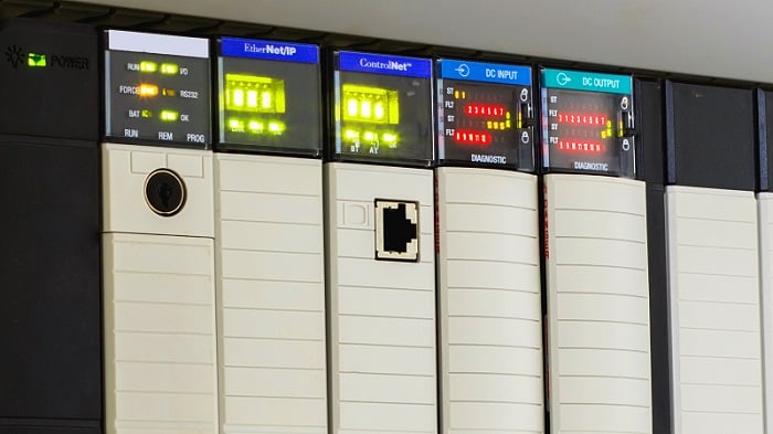
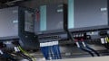
Figure 1. PLC status information can be viewed on the CPU and in memory. Image used courtesy of Adobe Stock
What are Some Common System Values?
The following list includes some of the more common data points found across many PLCs.
First Scan Bit
Is true only on the first scan after power-up or after changing execution mode to Run. It is often used to set initial values for variables and raise flags that can indicate power losses or mode changes.
Clock Time
Provides a readout of the current time (rather than using timers for tracking purposes). This is usually in an integer or dedicated time data type.
Execution Mode
This bit or integer indicates whether the CPU is in Program, Stop, or Run mode. Note that while this is useful information, the tags usually only update in Run mode, so be aware of delays in mode change system values. Some PLCs will provide separate bits to show software vs. hardware mode changes.
Errors
Errors will usually announce themselves as LEDs, but if you need access, say for an HMI or remote dashboard, these values can indicate the type, location, and severity of faults and errors.

Figure 2. Understanding faults can be critical to troubleshooting. Image used courtesy of Adobe Stock
Scan Times
Having access to the scan time is extremely important. Some PLCs include this data as an automatically tracked value, while others require the user to create a routine, saving CPU resources when it's not necessary.
CPU Information
Model number, firmware version, and even the currently running program name are often available for access or display on a remote panel, even when the programming software is not easily accessible.
How to Access System Values
Each manufacturer provides different access to values.
Directly as Tags
If these system values are in the tag listing, they are very convenient for any sort of logic command. Still, they can also clutter up the tag menu experience, so not all of them are immediately visible.
Some PLCs have system tags that are not listed in the tag menu, so they can only be entered by typing them into command fields.
Retrieved by Instructions
Some PLCs require instructions to retrieve the system values and store them in a user-created tag. This is very helpful for user-defined instructions, where words can be read and mapped efficiently with consistent instructions, rather than referencing individual tags.
Examples of System Values
Here are a few concrete examples with brands that should be familiar to many readers.
Rockwell Studio SLC 500 CPUs
In these address-based PLCs, all status information is in the S: file. This file is divided into many words (16-bit registers), each of which represents bits or integers that reflect I/O, CPU, and network status and fault information. A word-level description of all of these Status file contents can be found here.
Rockwell Studio 5000 CPUs
The First Scan bit is available as a directly written tag, called S:FS.
We can access other system values using the Get System Value (GSV) and Set System Value (SSV) commands.
The GSV command requires a Class Name and an Attribute Name. To get the controller status information, use the ControllerDevice class and the Status attribute. This status is a 16-bit integer, so the command will save the INT into a new INT tag that must be created. In this new INT tag, expand the bits and examine each one to translate the data. The breakdown is complex and found in the documentation, but it is also summarized in the table below.
| Standard INT structure: 2# 0000_0000_0000_0000 | ||||
| 00 | 00 | 0000 | 0000 | 0000 |
| Bits 15..14 | Bits 13..12 | Bits 11…8 | Bits 7…4 | Bits 3…0 |
| 01 = Modes Changing | 01 = Switch in Run Mode | 0001 = Rec Minor Fault | 0000 = Reserved | Reserved |
| 10 = Debug Mode | 10 = Switch in Prog Mode | 0010 = Unrec Minor Fault | 0001 = Flash in Progress |
|
|
|
11 = Switch in Rem Mode | 0100 = Rec Major Fault | 0010 = Reserved |
|
|
|
|
1000 = Unrec Major Fault | 0011 = Reserved |
|
|
|
|
|
0100 = Flash bad |
|
|
|
|
|
0101 = Faluted Mode |
|
|
|
|
|
0110 = Run Mode |
|
|
|
|
|
0111 = Program Mode |
|
Table 1. ControlLogix/CompactLogix status information.
Siemens S7-1200
The S7-1200 provides function blocks that retrieve specific values, such as system time, run/stop mode, and errors. These function blocks have separate names for each task, including Get_IM_Data, which returns CPU ID information; LED, which returns the CPU execution mode; GetStationInfo, which provides IP address information; and others.
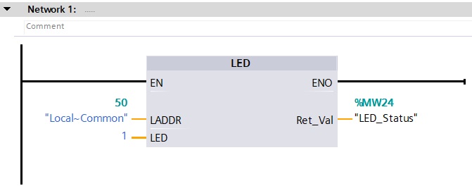
Figure 3. LED status of Run and Stop modes in a Siemens PLC.
This listing also applies to the S7-1500, and a full listing of those instructions is found in the online help guide.
AutomationDirect Productivity
In this PLC, the system values are readily available as tags. A full list and description of the tags can be found in the application help and in online help documentation.
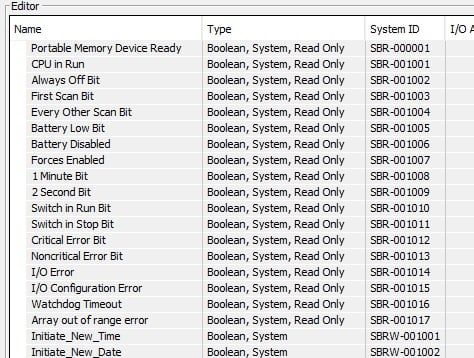
Figure 4. Sample of AutomationDirect system tags.
The Right Data For the Right Task
This information might not be the most commonly used data in the PLC, but it can be vitally important when trying to identify subtle ways to improve code, especially when working with many other remote modules for control and display.
For various other PLCs, it may be a bit of a trick to find the right bits to monitor CPU execution or retrieve diagnostic information. Do you have experience in finding system values in another PLC? I’d love to hear it, and it may help out someone else in the future.
Related Content