Facebook
 Google
 GitHub
 Linkedin
Understanding Power Factor Correction in Single Phase and Three Phase
In today's modern, digitally connected world, reliable and continuous power availability, together with power quality, help optimize power consumption hence improving distribution system efficiency.
What Is Power Factor (PF)?
Our previous power factor article describes the fundamental concept of power types along with power factor lagging vs. leading and the consequences of bad power factor.
In short summary, the power factor is the ratio of the power needed to do the useful work (also called true or real power, ‘P’) by electric equipment at the consumer end against the power delivered by the power utility facility (called apparent power, ’S’).
A good power factor determines the design quality and effective use of electric power, while a poor power factor indicates poor utilization of electric power. So there is a logical rationale that electric regulatory bodies impel to improve the power factor because a bad power factor is a real threat to the modern electric distribution system causing frequent power failures and losses.
Types of Electrical Load
As we already know, there are three types of electric loads: inductive, resistive, and capacitive, or an amalgam of all three.

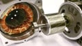
Figure 1. Most loads, like a motor, are inductive in nature, meaning that most power factor correction must negate the inductive reactive effects. Image used courtesy of Canva
In the present day, the most common loads in the electric distribution system are inductive devices like motors, generators, transformers, etc.; therefore, the reactive load in the power grid is constantly increasing. The increase in the power of transformers, motors, and generators leads to an increase in reactive power, so the control of reactive power load has become imperative.
Returning to power factor, the PF depends on the relative phase of the voltage and current, which can be inductive (where current is lagging) or capacitive (current is leading). It is important to root out what elements cause the poor power factor. There are two main causes: displacement and distortion.
Displacement occurs when voltage and current are out of phase due to the presence of inductive and capacitive components called reactive elements. It is caused by the linear load. Linear loads draw sinusoidal current, and the current is proportional to the voltage at all times.
Distortion is the outcome of harmonic distortion caused by a non-linear circuit such as a rectifier. In non-linear loads, the current is drawn in abrupt short pulses, distorting the current waveform.
What Is Power Factor Correction (PFC)?
PFC is a methodology used to improve the device’s power factor or increase the power factor of the load, thereby reducing the current drawn from the mains and improving the efficiency of the distribution system.
PFC is a technique that deploys different types of devices like capacitors to minimize the reactive power of an AC circuit to improve the efficiency and power factor.
There are two types of power corrections: single-phase and three-phase correction.
In a single-phase system, such as in homes, the capacitor bank is connected in parallel with the load, which helps to reduce reactive power and improve the power factor. It is important to select the suitable type and size of the capacitor.
In a three-phase system, the capacitor bank is connected in parallel with the load in a star or delta scheme for power factor correction. The banks automatically switch on and off to maintain a desired power factor.

Figure 2. A three-phase load system with a delta-connected capacitor bank.
Benefits of Improving Power Factor
Multiple benefits can be achieved by applying power factor correction:
- when a load absorbs a small amount of Q compared with P, the power utility profits from smaller cables, transformers windings, and generator windings
- reduced utility bills for domestic and industrial users
- extra KVA is available from the existing supply
- increased system capacity, power quality, energy saving, and cost saving
- increase to the system's current carrying capacity
- trimming losses in the distribution equipment
- reduced voltage drop in long cable
- improved equipment life by reducing electrical burden.
- fewer failures and downtime
Correcting Power Factor
Once again, the two main causes of low power factors are displacement and distortion. To remove the displacement factor, external reactive components are commonly used to compensate for the reactive power in the circuit. There are multiple methods for power factor correction, and the selection of the approach depends on the system requirement. The engineers may use combinations of techniques to achieve power factor correction.
Capacitor Banks
In industry, the majority of the inductive loads are motors and transformers. Automatic power factor correction (APFC) panels or capacitor banks are used to improve the power factor. So then, why do we use a capacitor bank? The capacitor bank is one of the most common methods to correct and improve the PF by providing the reactive power that needs to be supplied by the source utility.
Inside any industrial system, we have both active and reactive powers. If the percentage of reactive power is high, then the system is inefficient, and the power factor will be low. So the reactive power has a direct relationship with the power factor; therefore, we should lower the percentage of reactivity to improve the system efficiency.
The inductive loads produce lagging reactive power (current lag voltage, lagging PF). To compensate for lagging reactive power in the system, we produce leading reactive power in the system with capacitors. The leading and lagging reactive power both compensate or cancel each other and is called reactive power compensation.

Figure 3. Capacitor banks may serve facilities or branch circuits, each chosen specifically for the reactance of its own loads. Image used courtesy of Canva
Power Factor Correction Controller
This is a controlling device that permanently monitors the reactive power of the plant and automatically adjusts the reactive power to meet the desired power factor.
The controller activates the control functions by connecting or disconnecting the capacitor banks depending on whether the PF increase or decreases. If the power factor is less than the required values, the control automatically adds the capacitor bank in the circuit to improve the PF. The controller also displays multiple real-time parameters, which are easy to monitor, like current, voltage, power, etc.
Static Var Compensator (SVC)
These are power devices that provide reactive power compensation to improve the power factor by injecting or absorbing the reactive power into the electrical system to match the desired voltage level. The main components of SVCs are a thyristor-controlled reactor (TCR), which is used to control the inductive reactive power, a thyristor-switched capacitor (TSC) is used to control the capacitive reactive power, and a harmonic filter. They are typically used for large industrial loads, such as motors and transformers.
Poor Power Factor
The reason for poor power factor is generally caused by linear loads like inductions motors, transformers, and generators and has multiple disadvantages:
- excessive energy costs due to low power factor and penalties imposed by regulatory bodies
- poor power factor means drawing more power from the electricity networks to do the same work, so the cables and equipment need to be larger
- increased losses (high power means excessively high current) and overheating of transformers, switches, and cables
- increased voltage drop
- frequent tripping of breakers and fuses
- reduction in available power
Power Factor Correction Equipment
There are also some risks associated with the power correction devices if these devices are not properly installed by trained or qualified experts in the light of the manufacturer's instructions manual:
- improper installation can cause an electric shock, short circuit, and fire hazard
- malfunctioning of the device itself
- poor configuration of the device can cause overcorrection, which will increase the voltage level above the acceptable limits and could damage the equipment
- the device could be damaged if exposed to power surges
- it can introduce harmonic currents and harmonic distortion in the electrical system and can cause the failure of electrical equipment
- capacitors have a limited life expectancy, and fire may result without warning

Figure 4. The view from an oscilloscope can measure the time delay (leading and lagging) between voltage and current waveforms. Image used courtesy of Canva
Power Factor Measurement
Measuring PF in a facility to record change over time shows how effectively electrical power is being used. This will allow the engineer to take corrective measures, e.g., installing specialized equipment to increase electrical efficiency near the ideal target of unity power factor.
Multiple instruments can be used to monitor PFC in the system, like power factor meters, to measure and monitor the system's power factor in real-time—likewise, the AC voltmeter and AC ammeter measure system voltage and current. Active and reactive power transducers can be used to integrate the signals into the control system to record values for trends.
Power quality analyzers measure electrical quantities like voltage, current, power, apparent power, power factor, and harmonic distortion.
Finally, oscilloscopes can analyze the voltage and current waveforms to determine the power factor of the system.
Using proper meters and instruments, the monitoring of voltage, current, and power trends at the HMI level can indicate the success of PFC.