Facebook
 Google
 GitHub
 Linkedin
Tutorial: Rockwell’s Micro800 PLCs With FactoryTalk Design Workbench
Learn how to configure a connection and download a simple digital I/O project using the newest Rockwell software, paired with the Ethernet version of the Micro800 PLC lineup.
Learning a new PLC system is indeed a large undertaking for any control system engineer. Sure, the more controllers you’ve used, the easier it is to learn a new platform, but it always helps to have a bit of guidance when getting started.
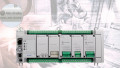
In this tutorial, we’ll set up a Micro820 PLC, specifically, a 2080-L20E-20QWB. Breaking down the part number, this PLC has 20 built-in I/O terminals (of varying uses), the E stands for Ethernet, and QW means digital DC inputs and relay outputs, respectively. Some of the I/O can also be used for analog signals—a very capable, yet simple PLC.
The FactoryTalk Design Workbench is the latest version of the Connected Components Workbench software, a free alternative to RSLogix/Studio 5000. Still, it is intended only for certain models of the Micro800 series, including the Ethernet version.
We will configure the port to accept an Ethernet connection to the PC, then download a very simple program that energizes a digital output when a digital input is activated.
Install the PLC
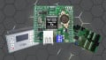
For my application, I will be using the simulator board provided with the PLC demo kit, but we’ll see how to install any pushbutton or switch in a similar manner.
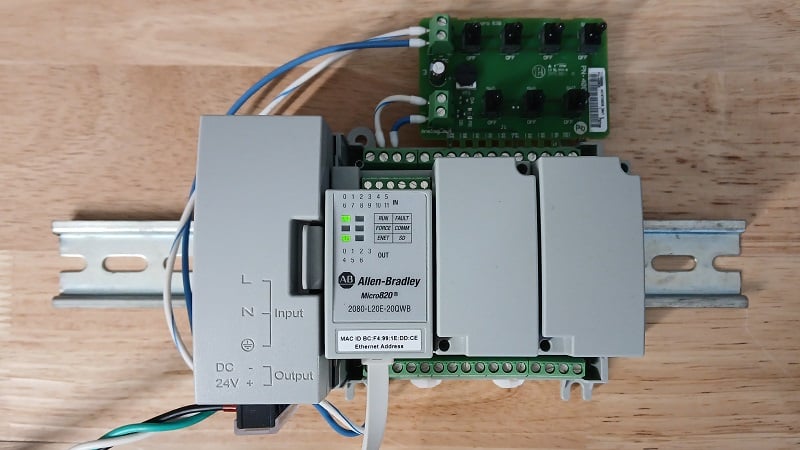
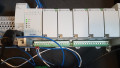
Figure 1. Micro820 with simulator I/O board.
The PLC requires 24 VDC to run. Using a standard industrial power supply, provide + and - 24 volts to the two left-hand terminals on the bottom of the PLC (viewed from the top).
For such a simple example project, we only need an input device; the indicator LEDs will be sufficient to test and verify the program when it’s working later.
If you don’t have the demo board from the starter kit, simply connect a pushbutton contact to 24 volts and connect the other side to the terminal labeled I-04. This will be input 4. We will use that input for this project, since inputs 0-3 work for both digital and analog inputs, so we’ll keep it simple for this first tutorial. Finally, connect the terminal labeled COM0 to the -24 VDC of the power supply.
Turn on the power supply, and the PLC power LEDs should light up. If so, we can move on to configuring the coms.
Set the IP Address of the PLC
First, we’ll discuss the com options briefly. On this PLC, we have two programming ports: USB and Ethernet. USB is a simple, easy option that requires zero configuration. However, Ethernet is more practical in the real world. To leverage the network advantage, we’ll initially connect via USB in order to set the IP address. From then on, we’ll use Ethernet exclusively.
Connect the USB-C port to your PC with a data-rated cable. It can be powered on or off when you connect the cable, but make sure it’s powered up at this time.
Note: Many phone charging cables supply power only, so they will not work here. Try plugging your phone into your laptop with the cable; if you can navigate the folder, it is indeed a data cable.
Open RSLinx Classic and go to RSWho. This window displays all the appropriate device drivers; USB should be in the list, as well as ETH and/or ETHIP (especially if you’re a former RSLinx user). If no USB device appears in the list, click Add a Driver, then select USB.
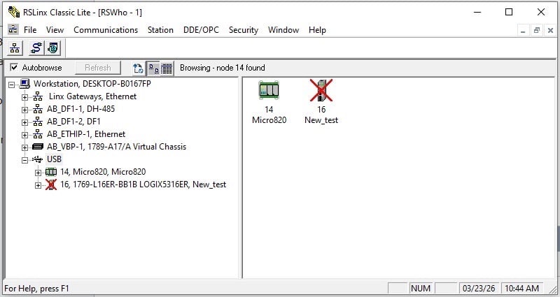
Figure 2. USB Driver in RSLinx Classic.
Expanding the USB device list should, after a few seconds, reveal your new PLC. Right-click the PLC, go to Module Configuration, then Port Configuration, and you should see some default settings.
By default, these PLCs will look for a dynamic address (DHCP). You may choose (as I have) to select a static IP address and set it to the same subnet as your PC's network card, only with a different last number. When you finish, press OK.
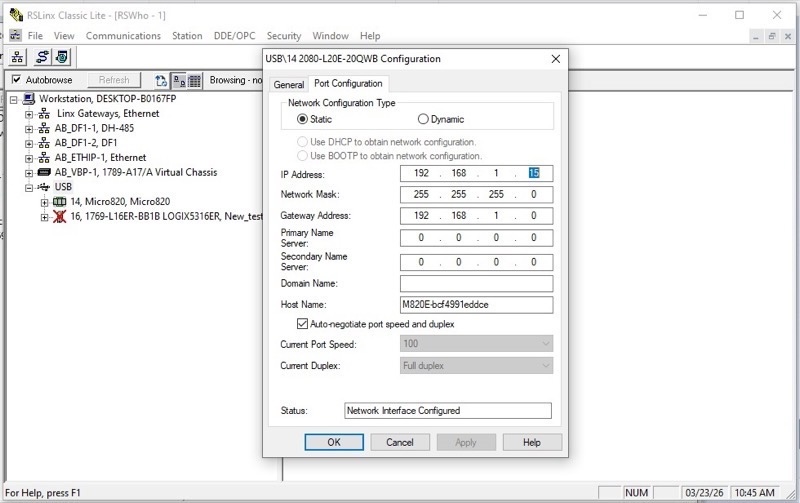
Figure 3. Setting the IP address over USB.
To test this address, disconnect the USB cable, and the device should disappear from the list, replaced with a red X icon. Next, install the Ethernet cable and expand the ETHIP driver list. The PLC, with its new IP address, should now show up in this list. If so, great job! Now we move to programming.
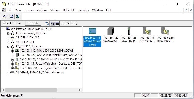
Figure 4. Verifying the correct IP address.
Writing a PLC Program
Open FactoryTalk Design Workbench and start a new project. I’ll name mine: First_Test. We will add a device on creation, but don’t go too quickly here–we can easily “Discover” the PLC, instead of adding it manually, which runs the risk of overriding the existing PLC and destroying our design work.
Click OK, then in the next window, click Discover in the top-right corner. Expand the ETHIP driver, then select the PLC with the IP address you recently designated. It’s probably the only Micro820 in the list. Click OK, and the creation process will complete.
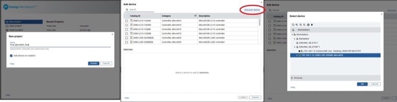
Figure 5. Creating a new project (left), discovering the live PLC (center), and locating the correct device (right).
At this point, there are two options:
- If this is a brand-new PLC, there will be no programs within the Programs menu on the left sidebar. Blank slate, ready to go.
- If this is a used or previously tested PLC, expand the Programs menu, and there may be one or more items. To get us back to that blank slate (fair warning: this will delete programs in the PLC), go offline using the connection button on the right. Right-click any named programs and delete them. Go back online, and the program will prompt you to download the current project. Click Yes.
Now we can go offline and right-click Programs to create a new one; I’ll call mine Hello_World_Test with the type Ladder Diagram, since this is intended as a primer for those with more traditional PLC experience, where LD is a major player.
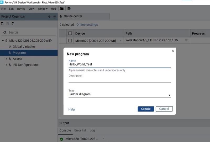
Figure 6. Creating the new ladder program.
Double-click on Hello_World_Test, and we are presented with the LD window. The Toolbox on the right side contains the command elements. Drag an XIC to the rung, followed by an OTE.
For the XIC, provide the name _IO_EM_DI_04 (this translates to: I/O port, embedded, digital input, port 04). For the OTE, following this same logic, type _IO_EM_DO_00 for the first output.
Click the button on the right side to Go Online, and choose to download the current project. Ensure the controller mode is Remote Run, and the PLC should now operate as expected!
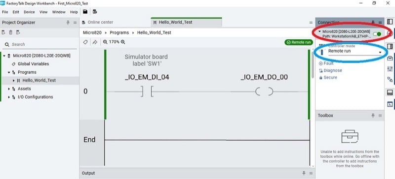
Figure 7. The final ladder diagram and the controls for connecting (red) and activating Remote run mode (blue).
Micro800: Next Steps
This has given us a successful, but very rudimentary program. In the next article, we’ll take a look at the variable list, how to alias tags, and how to make use of the analog input terminals of the Micro800 PLCs.
All images used courtesy of the author