Facebook
 Google
 GitHub
 Linkedin
Supervisory Control: How Commands Operate Real-world Objects
In power generation facilities, operational commands are issued, then make their way to the final real-world breakers, before feedback commands relay the position back to the control system.
In today’s era of digital transformation, new power plants and substations are well equipped with control systems purposely designed for supervisory control and monitoring. This supervisory control is performed through commands to operate real-world equipment such as circuit breakers, isolators, earth switches, start/stop commands, and the regulation of gates.
This equipment control has a sequential top-to-bottom scheme, starting from the operator workstation, proceeding through the control device (RTUs/PLC), and ending at the field devices. The commands must pass various interlocks, which could be hardware or software-based, and some preconditions of operations, along with some authorization checks. The commands become physical reality via the DO card or the digital relays (IED). Finally, a feedback status signal (00/01/10/11) is sent back to the control system to update the graphical status for the operator's information.
The hardwired scheme is used to send commands to operate the objects via a PLC/RTU, which may have one or more digital output (DO) cards, and an interposing/auxiliary relay is installed in the field for operating electrical equipment. The DO cards can be 8- or 16-channel, but old legacy DO cards can be equipped with a maximum of 32 channels. The 2nd method includes intelligent electronic devices (IEDs) instead of PLC-driven auxiliary relays. The latest IEDs support IEC 61850 and can send data to the RTU gateway/SCADA following a client/server model.
Device Control
Device control is a reference to the operator monitoring and controlling the power plant's critical objects from the SCADA GUI display, and sending operating commands (open/close, start/stop, on/off, etc.) to field devices such as isolators, breakers, bus couplers, etc. For a simple analogy, a remote that operates a TV or radio, turning it on/off or changing the channels remotely, is an example of device control.
Typical commands used for control can be set to one of two states (ON/OFF) corresponding to the two possible physical states of a breaker/isolator. Various checks are performed before sending a final command to prevent unintentional activation, which could initiate a tripping sequence.
The following validation steps are performed for command execution from the operator console.
- The operator selects an object such as a breaker, isolator, etc.
- The object is defined as ‘controllable’ on the HMI screen, which means operators can click on it.
- The user must have the authority to operate on that object. The authority can be set to administrator, operator, and viewer roles, etc.
- For safety purposes, the breaker operation (open/close) should be blocked during maintenance activity or when equipment is under testing.
- The operation of the same object from different consoles or locations is not allowed at the same time.
- When the operator selects the breaker, a small pop-up dialogue window appears, waiting for confirmation of the command from the operator.
Different dialogs or pop-up window templates are provided for various control devices; the following are a few examples:
Open/Close: Open/close command buttons to the breakers and isolators.
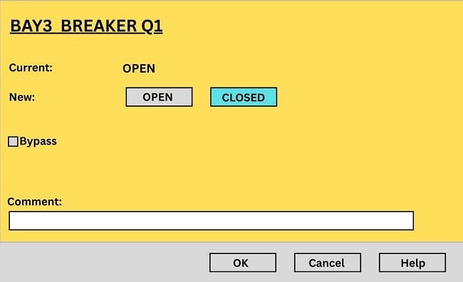
Figure 1. Example of an Open/Close dialog box. Image used courtesy of the author
Raise/Lower: Used to raise/lower pulses to the speed level adjustment, wicket gate limit/position, and voltage regulation, etc. The advantage is the step-by-step regulation of the process instead of abrupt changes in regulation.
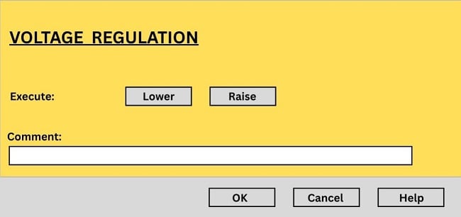
Figure 2. Example of a gate Raise/Lower dialog box. Image used courtesy of the author
Start/Stop: Used to issue start/stop commands to the motor, pumps, etc.
Block/Unblock: The user can block/unblock commands for breakers and isolators during maintenance.
Set-point: The operator can enter the MW (Megawatt) set point for individual generating units or a group of units.
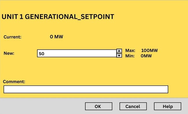
Figure 3. Example of a numeric set-point dialog box. Image used courtesy of the author
Commands: Data Engineering
Data Engineering of the command is defined through the Data Engineering tool, together with the definition of indications. The following data is defined for each indication that has an associated control output:
- Signal ID
- Hardware address
- Single-channel or double-channel indication
- Command pulse length
- Inverted or standard output
- One- or two-step command (immediate execution or check-before-execute)
- Time-out for supervision of the responding indication
INDICATION.CONTROL_TYPE: this option enables or disables the option of whether the checkback is performed before the command is executed or not.
INDICATION.NORMAL_STATUS: states the normal status of the indication. It means the status of the corresponding device is considered normal. The default values are:
00 is the abnormal status for double indication.
01(ON) is the normal status for on-state indication.
10(OFF) is the normal status for off-state indication.
11 is the abnormal status for the indication.
Control Through Digital Output Cards or IEDs
With the passage of time, the adoption of advanced technology, and the entry of OT devices in plants, the control philosophy has been evolving continually.
In simple terms, at the plant level, there are two basic ways to operate any breaker or isolator.
The first operation method is to use a DO card to implement the command issued by the operator from the operator workstations. This scheme may include the following components from top to bottom, on how commands are routed to the field.
- The operator clicks on the GUI page to open/close the line isolator.
- From the software/server, the command is received at the RTU/PLC level.
- The DO card activates the respective channels for the control object.
- An interposing relay and its contacts are used to operate high-voltage devices.
- Interlocking is also hardwired while opening and closing the breaker.
- In the end, the breaker/isolator is opened or closed.
- The feedback status of the breaker is also reported back to the main SCADA system, so that the control object is made ready for the next command.
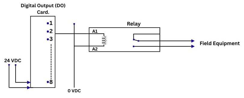
Figure 4. Handling of the command using the DO card and the interposing relay to operate the field equipment. Image used courtesy of the author
The second operation method results from upgrading an obsolete control system to digital IEDs. The following steps are necessary to execute commands to operate a breaker from the operator console.
- The operator from the workstation can manually select the breaker and issue the open/close command.
- From the workstation to the SCADA server, the server processes a command request and transmits it to the RTU/PLC over TCP/IP.
- The PLC/RTU receives the command and relays it to the relevant IED using the MMS (Manufacturing Message Specification) protocol.
- The IED receives and operates its output contact to open the breaker, and the relay can perform some interlock checks if necessary.
- The IEDs send a feedback signal to the SCADA server; as a result, the breaker status on the operator workstation is updated, and the object is ready for the next operation.
Issuing Commands
Providing activation energy to breakers and isolators will never be entirely virtual; hardwired connections will always be necessary. But the methods of interfacing with these devices, like PLC/RTU or IED, will be changing as technology allows more distributed, faster control of the end control devices.
Featured image used courtesy of Adobe Stock