Fluctuating on MW

M

Thread Starter

meshal

Our power plant consists of two frame 5 GE gas turbines running on part load. The load of the units vary from 10 to 13.5 MW /each unit. This week, we have observed fluctuating of MW of both units when the load of GT1 reach 11.5 MW and when we decrease or increase its load, the system become stable. What is the probable cause of this hunting? (Note: we are using distilled fuel oil and all filters are OK.)
 
There is not enough information.

Is either of your units running in Isochronous Mode?

What is happening to the frequency of the grid/units when the power output is unstable?

What is controlling the load of the units? An external (4-20 mA signal; RAISE/LOWER contact input signals; etc.)? Why does the output vary if the units are operating in Droop Speed Control mode?

If the units are both in Droop speed control and the grid is "small" and an Isochronous unit is controlling grid frequency, how is it behaving?

Are the hydraulic filter(s) clean on Unit 1? Is the hydraulic accumulator properly charged and valved in?

Was either of the units recently "worked on"--that is, was some kind of maintenance outage recently completed?

You say the units are running on Liquid Fuel; is the Liquid Fuel Forwarding pump(s) working properly?

Are the strainers upstream of the Liquid Fuel forwarding pump(s) clean?

Is there a pressure regulator between the discharge of the Liquid Fuel forwarding pump(s) and the High-pressure Liquid Fuel pump, and if so, is it working properly?

Is the Liquid Fuel pump clutch working properly (i.e., is it slipping as load increases)?

markvguy
 
Based on what you described, I assuming that both CTs are bussed together into a common transformer. If this is the case, it sounds like you're getting circulating currents. You may need to setup your voltage regulator in a droop configuration.

Did you notice speed fluxuations during this swing?

How are your units connected electrically? (together and to the grid)
 
P

Phil Corso, PE

Markvguy has already noted that information provided is not sufficient to solve the problem. But, if the problem has not yet been resolved, then, there is enough information to suggest a method of attack... plots of MW deviation vs time!

This will uncover whether the problem is mechanical in nature, i.e., turbine fuel control 'stiction'? Another cause, although less likely, is electrical instability in the form of load-angle swings! I stated 'less likely' because system inertia is relatively small for gas-turbine prime movers... and the problem did not exist at startup! Or, did it?
 
The original post says: "...This week, we have observed fluctuating of MW..." which implies this problem has NOT been occurring since start-up.

Wouldn't circulating currents be a problem which suggests either: 1) this might have been a problem which existed since start-up but didn't be come apparent until some fuel flow or -control problem at this particular system load exaggerated it, or 2) there is some fault developing in the transformer if the two units are bussed together upstream of a step-up transformer?

In either case, don't circulating currents usually manifest themselves as VAR swings, not load swings? Doesn't adjusting exciter regulator droop settings mainly stabilize VAR swings, not MW swings?

To the original poster, were you experiencing VAR swings/fluctuations of roughly the same period (frequency) as the MW swings?

markvguy
 
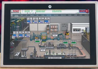
The two units are on droop control and (part load)is displayed on HMI screen.
The fluctuating is observed when the load of unit No.1 is between 11-12 MW.Usually,when we face this situation, we reduce its load to 10.5 MW. Grid frequency and VAR are normal when swing happens.

You will find below some information that may help to analyse the problem
-Fuel pump clutch was replaced two years ago on unit No.1
-Hydraulic oil system on the type that we have has no accumilators. (the gas turbine type is GE, NUOVO PIGNONE frame 5)
-Unit No.2 lube oil filter diff. pressure is 1.1 bar at this moment.
-One forwarding pump skid is used to supply both units.(it consists of three pumps- two running and one stand by - with one filter before pumps and one regulator after pumps)
-Unit No.1 has exceeded its HGPI with 4000hrs

If you need any extra information please write
thanks alot
 
P

Phil Corso, PE

Responding to Markvguy's Oct 6, 11:15am comments... 'circulating currents' is a whole separate subject! Furthermore, I don't believe it
is the cause of Meshal's problem! Following are my reasons:

1) Circulating currents are possible whether or not the neutrals are connected. Two conditions are necessary: a) the presence of a resultant
harmonic voltage; and b) a path for the current flow. And, if they're present now they would have been present at initial commissioning!

2) Even if both generators are neutral-grounded via resistors (normal for the size generator cited) the resultant current would increase MW
production by 0.1 to 0.2 percent.... an inappreciable value.

3) I agree with your observations regarding VAr fluctuations, but we must await further details from the author!

Regards,
Phil Corso, PE {Boca Raton, FL, USA}
[[email protected]] ([email protected])
 
This is the second time this year this author has been told, "It can't be the [insert part name here]; we replaced it [insert number here] years ago." What the #%&@?!?!?!

In the first case, the I/P (current-to-pressure "converter") had indeed failed again--likely because of the heat it was experiencing because of the steam leak which was blowing directly on it, but that was just a lucky guess....

There were a couple of liq fuel pump clutch solenoids: ones rated at 100 VDC and ones rated at 125 VDC. It's not clear when the manufacturer switched from 100 VDC coils to 125 VDC coils, but a couple of site have replaced 100 VDC coils with 125 VDC coils and have experienced problems.

The coils rated at 100 VDC require an in-line resistor to reduce the voltage being applied to the coil. In the Mk IV, the resistors were located in the <PDM>. In the Mk V and Mk VI, there are located on the door of the <PD> (not very easily accessible). If the coil is rated at 125 VDC, the resistor must be removed from the circuit (in the <PD>, it can be done by shorting the resistor).

Is your liq fuel pump clutch circuit properly configured for the rated voltage of the coil installed on your unit?

No hydraulic accumulator? Any hydraulic pressure problems which might be occurring will be exaggerated without an accumulator. You didn't mention if you'd checked the air bleed check-valve....

Hyd. Filter Pressure doesn't seem unusual.

Are there any Diagnostic Alarms being annunciated when the megawatt fluctuations are being experienced?

Are both the units supplied from the same Liq. Fuel Forwarding skid--including the pressure regulator? Because if both units are experiencing MW fluctuations (and it's not clear if they both are or not), and they're both supplied by the same forwarding system, then flow problems on one unit can be "transferred" to the other unit through the liquid fuel system.

Liq fuel forwarding piping systems are notorious for collecting air pockets in high points, and system designers are notorious for not putting vents in EVERY high point in the piping system. Have you bled the high point vents in the liq fuel forwarding piping? Are there vents in every high point?

You said there is a pressure regulator on the discharge of the forwarding skid, but you didn't say if the pressure was fluctuating when the MWs were fluctuating.

You didn't say anything about Liq Fuel Filters, and the differential pressures across them.

Liq fuel pumps wear out; servos wear out. You said the unit was well past its scheduled maintenance point.

These kinds of problems are NOT usually caused BY the control system. It's usually reacting to some kind of external stimulus. Just because the control system reports a fluctuating power output doesn't mean it's responsible for the fluctuating power output.

markvguy
 
The unit No1 has the answer, last week it was tripped by loss of flame. Fuel pump cluch was damaged. We have replaced the cluch and main fuel pump with new one and now no more fluctuation on the system.
 
Thanks very much for the feedback, Meshal! Feedback is the most IMPORTANT part of this experience--without it, no one knows if the solutions/advice offered was beneficial or not!

markvguy

P.S. Did you confirm the voltage rating of the fuel pump clutch coil--and confirm the dropping resistor should or should not be used with the clutch? It could be the reason the second clutch failed relatively soon after it was installed....
 
we test the new cluch operation by forcing L20CF1X, voltage was 125 vdc but we have not checked resistance. The old cluch output shaft was mechanically damaged, because of that we did not concentrate on the electrical side.
 
You may be able to measure resistance to compare with manufacturer's spec's to determine which voltage should be applied to the clutch. And it's not clear where you're measuring the voltage--at the clutch terminals or at the DTBC/DTBD TB.

If the clutch has a 125 VDC coil and you are applying voltage through the dropping resistor on the door of the <PDM>, you will not be applying enough voltage to the clutch coil and it will slip and operate as you described in your original post.

You can refer to the information in the Signal Flow Diagrams in Appendix D of the Mk V App. Manual, GEH-6195. If you have a later revision, possibly 'C' or 'D', you can find a very good description of the circuit for the Liq. Fuel Pump clutch circuit components in App. E-2.

markvguy
 
Top