It is possible to convey electrical power and communicate analog information over the same two wires using 4 to 20 milliamps DC, if we design the transmitter to be loop-powered. A loop-powered transmitter connects to a process controller with only two wires, which is why loop-powered transmitters are synonymously known as 2-wire transmitters:

Here, the transmitter is not really a current source in the sense that a 4-wire transmitter is. Instead, a 2-wire transmitter’s circuitry is designed to act as a current regulator, limiting current in the series loop to a value representing the process measurement, while relying on a remote source of power to motivate the electric current. Please note the direction of the arrow in the transmitter’s dependent current source symbol, and how it relates to the voltage polarity marks. Refer back to the illustration of a 4-wire transmitter circuit for comparison. The current “source” in this loop-powered transmitter actually behaves as an electrical load, while the current source in the 4-wire transmitter functioned as a true electrical source.
A loop-powered transmitter gets its operating power from the minimum terminal voltage and current available at its two terminals. With the typical source voltage being 24 volts DC, and the maximum voltage dropped across the controller’s 250 ohm resistor being 5 volts DC, the transmitter should always have at least 19 volts available at its terminals. Given the lower end of the 4-20 mA signal range, the transmitter should always have at least 4 mA of current to function on. Thus, the transmitter will always have a certain minimum amount of electrical power available on which to operate, while regulating current to signal the process measurement to the receiving instrument.
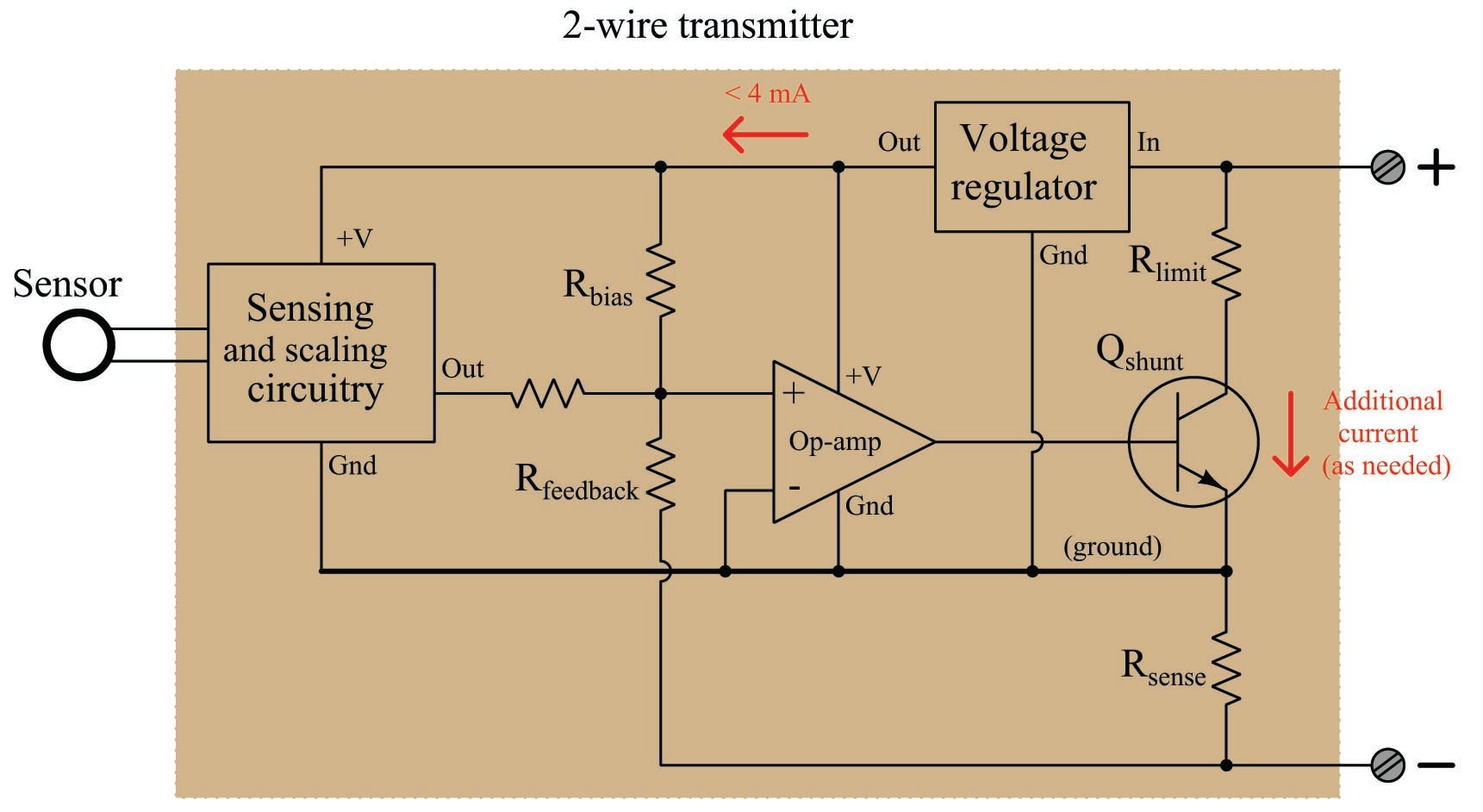
Internally, the electronic hardware of a 2-wire transmitter circuitry resembles the following (simplified) diagram. Note that everything shown within the shaded rectangle is represented by the “2-wire transmitter” circle in the previous diagram:

All sensing, scaling, and output conditioning circuitry inside the transmitter must be designed to operate on less than 4 mA of DC current, and at a modest terminal voltage. In order to create loop currents exceeding 4 mA – as the transmitter must do in order to span the entire 4 to 20 milliamp signal range – the transmitter circuitry uses a transistor to shunt (bypass) extra current from one terminal to the other as needed to make the total current indicative of the process measurement. For example, if the transmitter’s internal operating current is only 3.8 mA, and it must regulate loop current at a value of 16 mA to represent a condition of 75% process measurement, the shunt transistor will be driven by the opamp to bypass exactly 12.2 mA of current (because 3.8 mA + 12.2 mA = 16.0 mA).
The very low amount of electrical power available at a 2-wire transmitter’s terminals limits its functionality. If the transmitter requires more electrical power than can be delivered with 4 milliamps and 19 volts (minimum each), the only solution is to go with a 4-wire transmitter where the power conductors are separate from the signal conductors. An example of a process transmitter that must be 4-wire is a chemical analyzer such as a chromatograph, requiring enough power to operate an electrical heater, solenoid valves, and an on-board computer to process the sensor data. There is simply no way to operate a machine as complex and power-hungry as a 2010-era chromatograph on 4 milliamps and 19 volts!
Early current-based industrial transmitters were not capable of operating on such low levels of electrical power, and so used a different current signal standard: 10 to 50 milliamps DC. Loop power supplies for these transmitters ranged upwards of 90 volts to provide enough power for the transmitter. Safety concerns made the 10-50 mA standard unsuitable for some industrial installations, and modern microelectronic circuitry with its reduced power consumption made the 4-20 mA standard practical for nearly all types of process transmitters.
Hello,
Is the sensor fail if 24V is applied directly to the loop power sensor terminals?