 Facebook
 Google
 GitHub
 Linkedin
Electrical Signal and Control Wiring
There is much to be said for neatness of assembly in electrical signal wiring. Even though the electrons don’t “care” how neatly the wires are laid in place, human beings who must maintain the system certainly do. Not only are neat installations easier to navigate and troubleshoot, but they tend to inspire a similar standard of neatness when alterations are made.
The following photographs illustrate excellent wiring practice. Study them carefully, and strive to emulate the same level of professionalism in your own work.
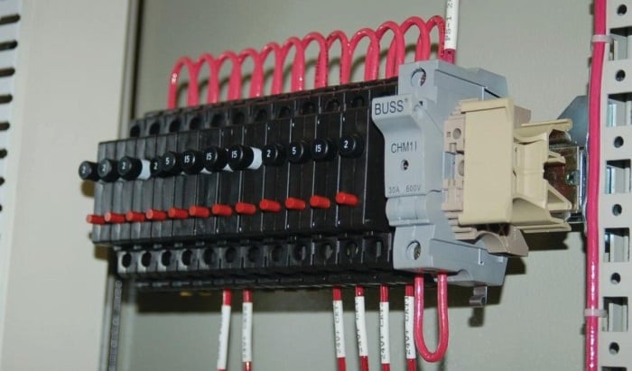
Here we see 120 volt AC power distribution wiring. Note how the hoop-shaped “jumper” wires are all cut to (nearly) the same length, and how each of the wire labels is oriented such that the printing is easy to read:
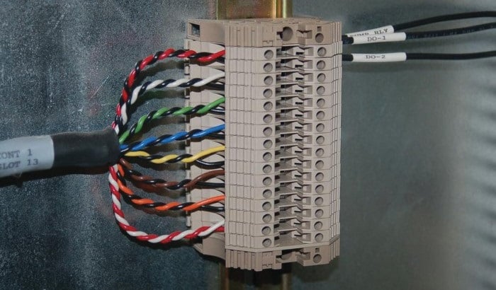
This next photograph shows a great way to terminate multi-conductor signal cable to terminal blocks. Each of the pairs was twisted together using a hand drill set to very slow speed. Note how the end of the cable is wrapped in a short section of heat-shrink tubing for a neat appearance:
Beyond aesthetic preferences for instrument signal wiring are several practices based on sound electrical theory. The following subsections describe and explain these wiring practices.
Connections and Wire Terminations
Many different techniques exist for connecting electrical conductors together: twisting, soldering, crimping (using compression connectors), and clamping (either by the tension of a spring or under the compression of a screw) are popular examples. Most industrial field wiring connections utilize a combination of compression-style crimp “lugs” (often referred to as ferrules or compression terminals) and screw clamps to attach wires to instruments and to other wires.
The following photograph shows a typical terminal strip or terminal block array, whereby twisted-pair signal cables connect to other twisted-pair signal cables. Metal bars inside each plastic terminal section form connections horizontally, so that wires fastened to the left side are connected to wires fastened to the right side:
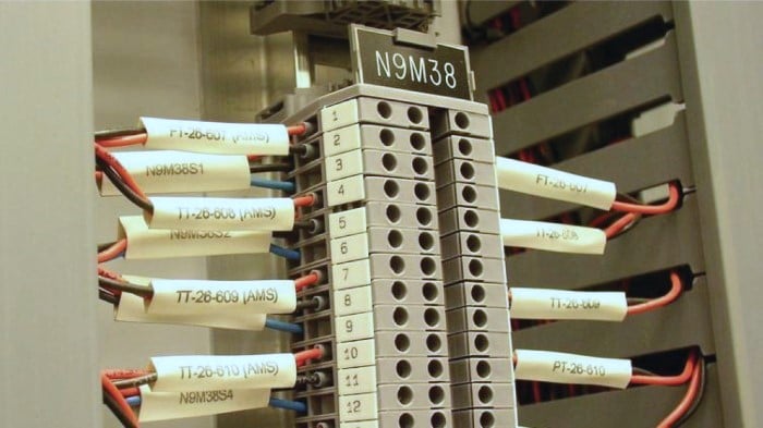
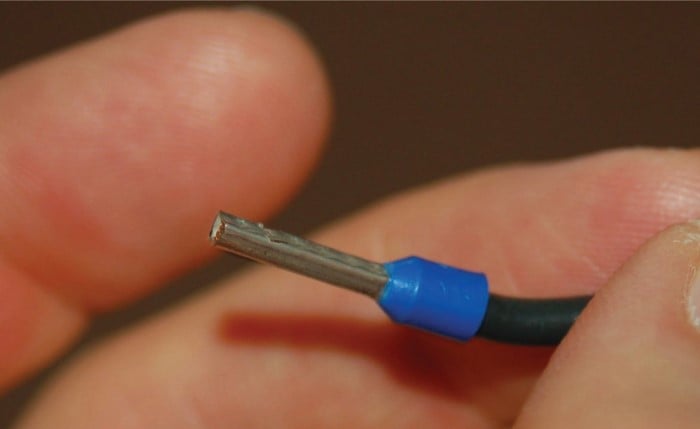
If you look closely at this photograph, you can see the bases of crimp-style ferrules at the ends of the wires, just where they insert into the terminal block modules. These terminal blocks use screws to apply force which holds the wires in close electrical contact with a metal bar inside each block, but metal ferrules have been crimped on the end of each wire to provide a more rugged tip for the terminal block screw to hold to. A close-up view shows what one of these ferrules looks like on the end of a wire:
Also evident in that previous photograph is the dual-level connection points on the left-hand side of each terminal block. Two pairs of twisted signal conductors connect on the left-hand side of each terminal block pair, where only one twisted pair of wires connects on the right-hand side. This also explains why each terminal block section has two screw holes on the left but only one screw hole on the right.
A close-up photograph of a single terminal block section shows how the screw-clamp system works. Into the right-hand side of this block a single wire (tipped with a straight compression ferrule) is clamped securely. No wire is inserted into the left-hand side:
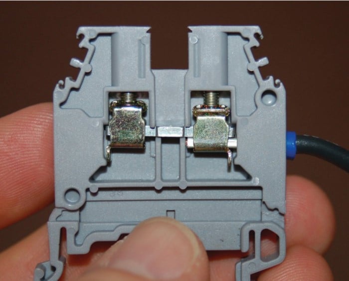
If another wire were secured by the screw clamp on the left-hand side of this terminal block, it would be made electrically common with the wire on the right-hand side by virtue of the metal bar joining both sides.
Some terminal blocks are screwless, using a spring clip to make firm mechanical and electrical contact with the wire’s end:
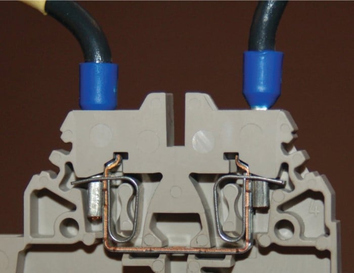
In order to extract or insert a wire end from or to a “screwless” terminal block, you must insert a narrow screwdriver into a hole in the block near the insertion point, then pivot the screwdriver (like a lever) to exert force on the spring clip. Screwless terminal blocks are generally faster to terminate and un-terminate than screw type terminal blocks, and the pushing action of the release tool is gentler on the body than the twisting action required to loosen and tighten screws.
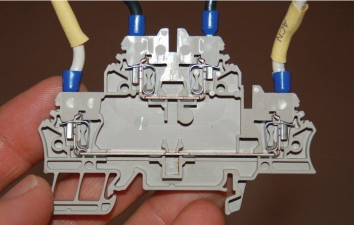
Many different styles of modular terminal blocks are manufactured to suit different wiring needs. Some terminal block modules, for example, have multiple “levels” instead of just one. The following photograph shows a two-level terminal block with screwless wire clamps:
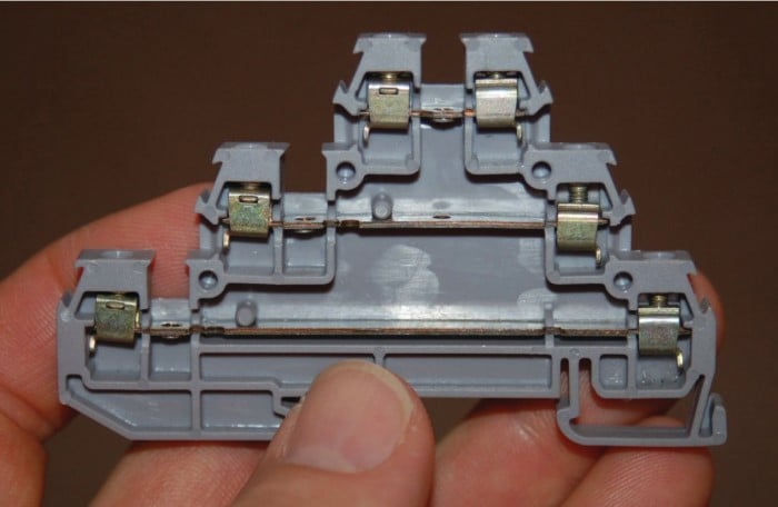
The next photograph shows a three-level terminal block with screw type clamps:
Some multi-level terminal blocks provide the option of internal jumpers to connect two or more levels together so they will be electrically common instead of electrically isolated. This use of a multi-level terminal block is preferable to the practice of inserting multiple wires into the same terminal, when wires need to be made common to each other.
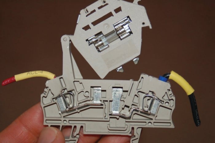
Other modular terminal blocks include such features as LED indicator lamps, switches, fuses, and even resettable circuit breakers in their narrow width, allowing the placement of actual circuit components near connection points. The following photograph shows a swing-open fused terminal block module in the open position:
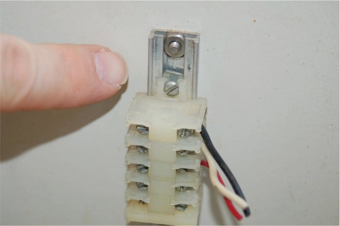
Modular terminal blocks are useful for making connections with both solid-core and stranded metal wires. The clamping force applied to the wire’s tip by the screw mechanism inside one of these blocks is direct, with no sliding or other motions involved. Some terminal blocks, however, are less sophisticated in design. This next photograph shows a pair of “isothermal” terminals designed to connect thermocouple wires together. Here you can see how the bare tip of the screw applies pressure to the wire inserted into the block:
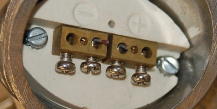
The rotary force applied to each wire’s tip by these screws necessitates the use of solid wire. Stranded wire would become frayed by this combination of forces.
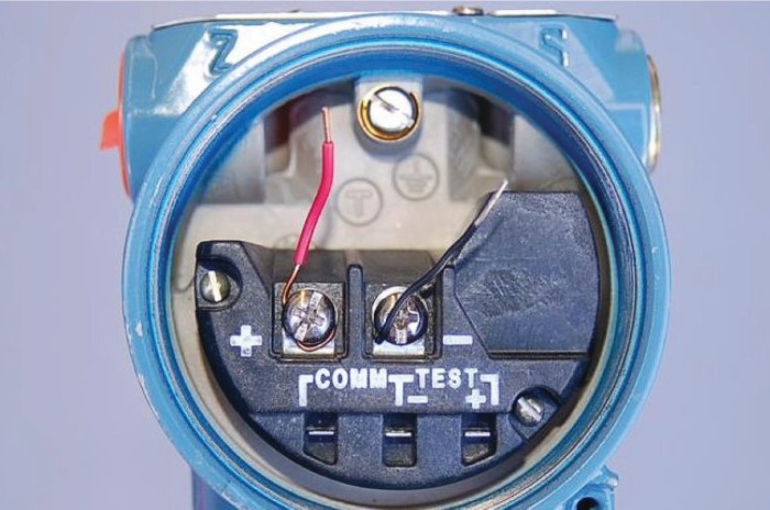
Many field instruments, however, do not possess “block” style connection points at all. Instead, they are equipped with pan-head machine screws designed to compress the wire tips directly between the heads of the screws and a metal plate below.
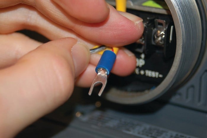
Solid wires may be adequately joined to such a screw-head connection point by partially wrapping the bare wire end around the screw’s circumference and tightening the head on top of the wire, as is the case with the two short wire stubs terminated on this instrument:
The problem with directly compressing a wire tip beneath the head of a screw is that the tip is subjected to both compressive and shear forces. As a result, the wire’s tip tends to become mangled with repeated connections. Furthermore, tension on the wire will tend to turn the screw, potentially loosening it over time.
This termination technique is wholly unsuitable for stranded wire, because the shearing forces caused by the screw head’s rotation tends to “fray” the individual strands. The best way to attach a stranded wire tip directly to a screw-style connection point is to first crimp a compression-style terminal to the wire. The flat metal “lug” (ferrule) portion of the terminal is then inserted underneath the screw head, where it can easily tolerate the shearing and compressive forces exerted by the head.
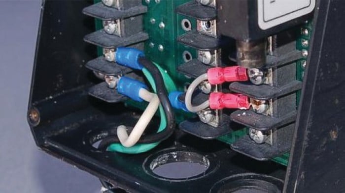
This next photograph shows five such stranded-copper wires connected to screw-style connection points on a field instrument using compression-style terminals:
Compression-style terminals come in two basic varieties: fork and ring. An illustration of each type is shown here:
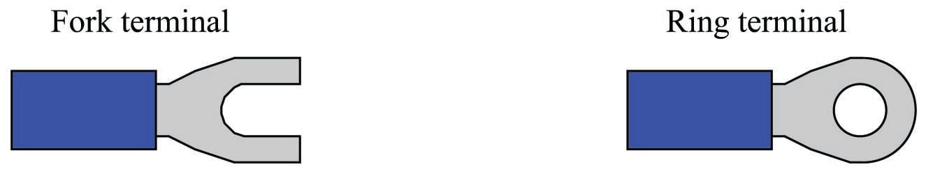
Fork terminals are easier to install and remove, since they merely require loosening of the connector screw rather than removal of the screw. Ring terminals are more secure, since they cannot “fall off” the connection point if the screw ever accidentally loosens.
Just as direct termination underneath a screw head is wholly unsuitable for stranded wires, compression-style terminals are wholly unsuitable for solid wire. Although the initial crimp may feel secure, compression terminals lose their tension rapidly on solid wire, especially when there is any motion or vibration stressing the connection. Compression wire terminals should only be crimped to stranded wire!
Properly installing a compression-type terminal on a wire end requires the use of a special crimping tool. The next photograph shows one of these tools in use:
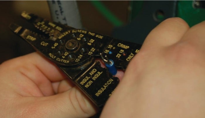
Note the different places on the crimping tool, labeled for different wire sizes (gauges). One location is used for 16 gauge to 10 gauge wire, while the location being used in the photograph is for wire gauges 22 through 18 (the wire inside of the crimped terminal happens to be 18 gauge).
This particular version of a “crimping” tool performs most of the compression on the underside of the terminal barrel, leaving the top portion undisturbed. The final crimped terminal looks like this when viewed from the top:
DIN Rail
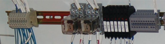
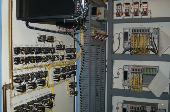
An industry-standard structure for attaching terminal blocks and small electrical components to flat metal panels is something called a DIN rail. This is a narrow channel of metal – made of bent sheet steel or extruded aluminum – with edges designed for plastic components to “clip” on. The following photograph shows terminal blocks, relay sockets, fuses, and more terminal blocks mounted to a horizontal length of DIN rail in a control system enclosure:
Two photographs of a terminal block cluster clipped onto a length of DIN rail, one from above and one from below, show how specially-formed arms on each terminal block module fit the edges of the DIN rail for a secure attachment:
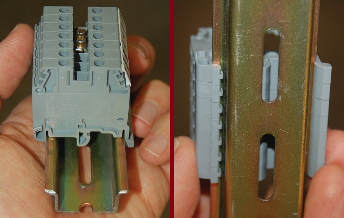
The DIN rail itself mounts onto any flat surface by means of screws inserted through the slots in its base. In most cases, the flat surface in question is the metal subpanel of an electrical enclosure to which all electrical components in that enclosure are attached.
An obvious advantage of using DIN rail to secure electrical components versus individually attaching those components to a subpanel with their own sets of screws is convenience: much less labor is required to mount and unmount a DIN rail-attached component than a component attached with its own set of dedicated screws. This convenience significantly eases the task of altering a panel’s configuration. With so many different devices manufactured for DIN rail mounting, it is easy to upgrade or alter a panel layout simply by unclipping components, sliding them to new locations on the rail, or replacing them with other types or styles of components.
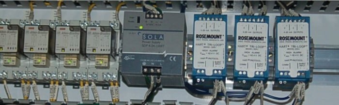
The next photograph shows some of the diversity available in DIN rail mount components. From left to right, we see four relays, a power supply, and three HART protocol converters, all clipped to the same extruded aluminum DIN rail:
As previously mentioned, DIN rail is available in both stamped sheet-steel and extruded aluminum forms. A comparison of the two materials is shown here, with sheet steel on the left and aluminum on the right:
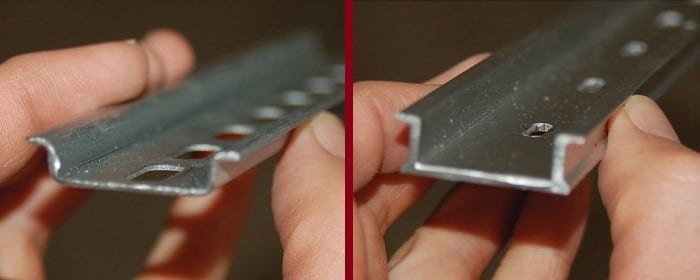
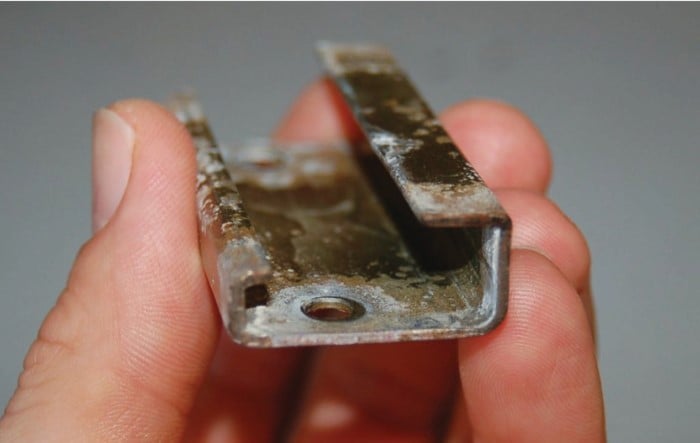
The form of DIN rail shown in all photographs so far is known as “top hat” DIN rail. A variation in DIN rail design is the so-called “G” rail, with a markedly different shape:
Fortunately, many modular terminal blocks are formed with the ability to clip to either style of DIN rail, such as these two specialty blocks, the left-hand example being a terminal block with a built-in disconnect switch, and the right-hand example being a “grounding” terminal block whose termination points are electrically common to the DIN rail itself:
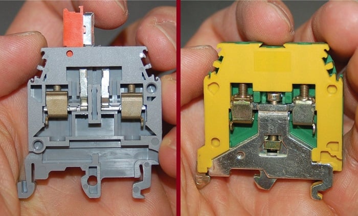
If you examine the bottom structure of each block, you will see formations designed to clip either to the edges of a standard (“top hat”) DIN rail or to a “G” shaped DIN rail.
Smaller DIN rail standards also exist, although they are far less common than the standard 35mm size:
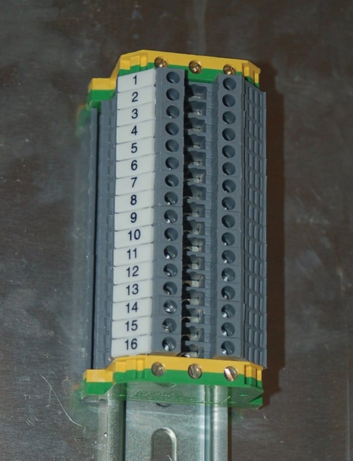
A nice feature of many DIN rail type terminal blocks is the ability to attach pre-printed terminal numbers. This makes documentation of wiring much easier, with each terminal connection having its own unique identification number:
Cable Routing
In the interest of safety and longevity, one cannot simply route electrical power and signal cables randomly between different locations. Electrical cables must be properly supported to relieve mechanical stresses on the conductors, and protected from harsh conditions such as abrasion which might degrade the insulation.
A traditional and rugged technique for cable routing is conduit, either metal or plastic (PVC). Conduit resembles piping used to convey fluids, except that it is much thinner-walled than fluid pipe and is not rated to withstand internal pressure as pipe is. In fact, threaded conduit uses the same thread pitch and diameter standards as NPT (National Pipe Taper) fluid pipe connections.
Metal conduit naturally forms a continuously-grounded enclosure for conductors which not only provides a measure of protection against electrical shock (all enclosures and devices attached to the conduit become safely grounded through the conduit) but also shields against electrostatic interference. This is especially important for power wiring to and from devices such as rectifiers and variable-frequency motor drive (VFD) units, which have a tendency to broadcast large amounts of electromagnetic noise.
Plastic conduit, of course, provides no electrical grounding or shielding because plastic is a non-conductor of electricity. However, it is superior to metal conduit with regard to chemical corrosion resistance, which is why it is used to route wires in areas containing water, acids, caustics, and other wet chemicals.
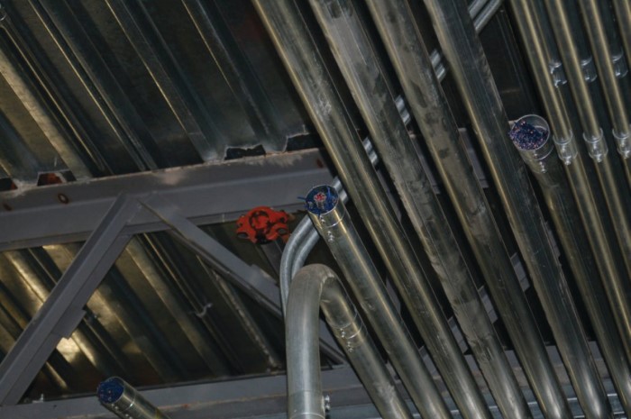
Thin-wall conduit is made with metal so thin that threads cannot be cut into it. Instead, special connectors are used to join “sticks” of thin-wall conduit together, and to join thin-wall conduit to electrical enclosures. Several runs of thin-wall conduit appear in this next photograph. Two of those conduit runs have been severed following a wiring change, exposing the conductors inside:
Installing cable into an electrical conduit is a task referred to as cable pulling, and it is something of an art. Cable “pulls” may be especially challenging if the conduit run contains many bends, and/or is close to capacity in terms of the number and size of conductors it already holds. A good practice is to always leave a length of nylon pull string inside each length of conduit, ready to use for pulling a new wire or cable through. When performing a wire “pull,” a new length of nylon pull string is pulled into the conduit along with the new wires, to replace the old pull string as it is pulled out of the conduit. Special lubricating “grease” formulated for electrical wiring may be applied to conductors pulled into a conduit, to reduce friction between those new conductors and the conductors already inside the conduit.
When connecting electrical conduit to end-point devices, it is common to use flexible liquid-tight conduit as a connector between the rigid metal (or plastic) conduit and the final device. This provides some stress relief to the conduit in the event the device moves or vibrates, and also allows more freedom in positioning the device with respect to the conduit. Here, we see a motor-operated control valve with two runs of liquid-tight conduit routing conductors to it:
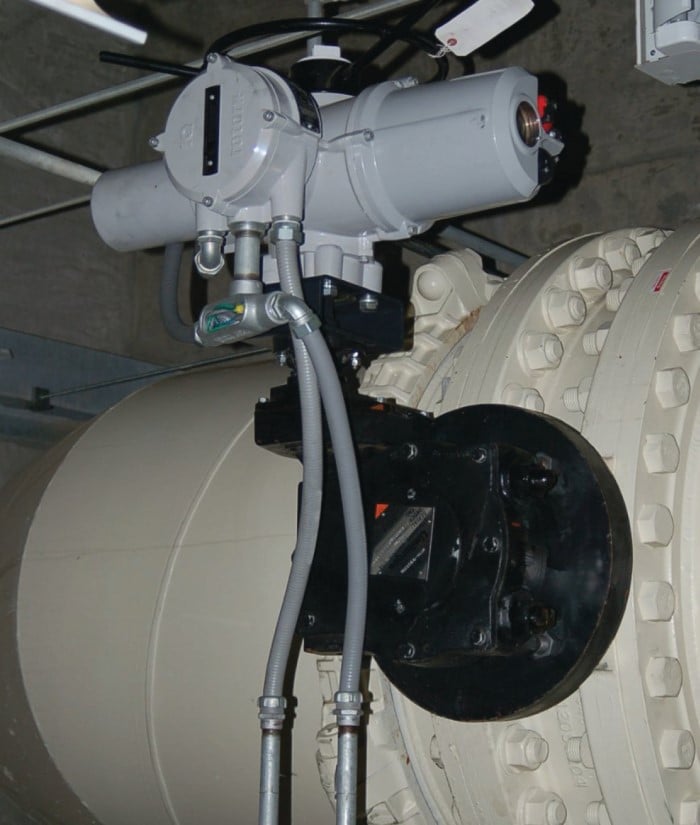
Liquid-tight conduit comes in two general varieties: metallic and non-metallic. The metallic kind contains a spiraled metal sheath just underneath the plastic outer coating to provide a continuously-grounded shield much the same way that rigid metal conduit does. Non-metallic liquid-tight conduit is nothing more than plastic hose, providing physical protection against liquid exposure and abrasion, but no electrical grounding or shielding ability.
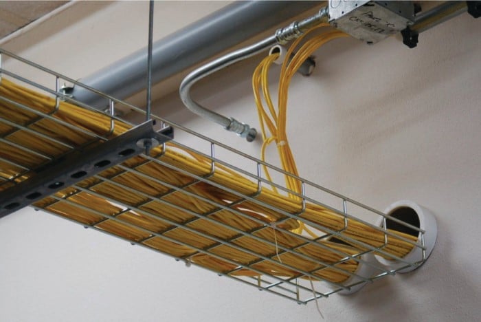
Another technique for cable routing is the use of cable tray. Trays may be made of solid steel wire for light-duty applications such as instrument signal cabling or computer network cabling, or they may be made of steel or aluminum channel for heavy-duty applications such as electrical power wiring. Unlike conduit, cable trays are open, leaving the cables exposed to the environment. This often necessitates special cable insulation rated for exposure to ultraviolet light, moisture, and other environmental wear factors. A decided advantage of cable trays is ease of cable installation, especially when compared to electrical conduit.
While cable tray does provide a continuously-grounded surface for electrical safety the same as metal conduit, cable tray does not naturally provide shielding for the conductors because it does not completely enclose the conductors the way metal conduit does.
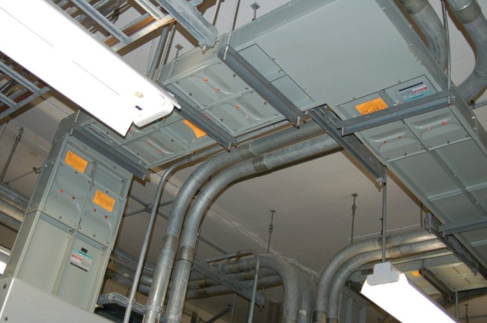
An example of light-duty cable tray appears here, used to support Ethernet cabling near the ceiling of a room at a college campus. The cable tray is made of solid steel wire, bent to form a “basket” to support dozens of yellow Ethernet cables:
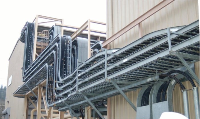
Heavy-duty cable tray appears throughout this next photograph, supporting large-gauge power conductors for electric generators at a gas turbine power plant. Here, the cable tray has the appearance of an aluminum ladder, with extruded metal rails and rungs providing physical support for the cables:
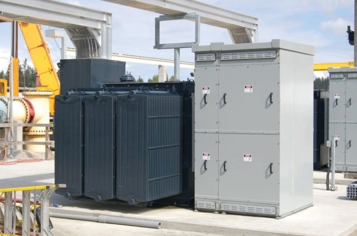
Similar cable trays appear in the next photograph, supporting feeder cables from a stationary transformer and switchgear cabinets:
A special form of wiring often seen in industrial facilities for power distribution is busway, also known as bus duct. These are rectangular sheet-metal tubes containing pre-fabricated copper busbars for the conduction of three-phase AC power. Special junction boxes, “tees,” and tap boxes allow busways to extend and branch to other busways and/or standard conductor wiring.
Busways are used in indoor applications, often in motor control centers (MCCs) and power distribution center rooms to route electrical power to and from large disconnect switches, fuses, and circuit breakers. In this photograph, we see a busway used to distribute power along the ceiling of an MCC room, alongside regular rigid conduit:
As useful and neat in appearance as busways are, they are definitely limited in purpose. Busways are only used for electrical power distribution; not for instrumentation, control, or signaling purposes.
Two materials useful for neatly routing power, signal, and instrumentation conductors inside an enclosure are wire duct and wire loom. Wire duct is a plastic channel with slotted sides, designed to be attached to the subpanel of an enclosure along with all electrical devices inside that enclosure. Wires pass from the devices to the duct through the slots (gaps) in the sides of the duct, and are enclosed by a removable plastic cover that snaps onto the top of the duct. A common brand name of wire duct in the industry is Panduit and so you will often hear people refer to wire duct as “Panduit” whether or not that particular brand is the one being used. Wire loom is a loose spiral tube made of plastic, used to hold a group of individual wires together into a neat bundle. Wire loom is frequently used when a group of conductors must periodically flex, as is the case of a wire bundle joining devices inside a panel to other devices mounted on the hinging door of that panel.
A photograph showing both wire duct and wire loom inside an instrumentation panel appears here. The wire duct is the grey-colored rectangular plastic channel set vertically and horizontally inside the panel, while the loom is a grey-colored plastic spiral surrounding the bundle of wires near the door hinge:
Signal Coupling and Cable Separation
If sets of wires lie too close to one another, electrical signals may “couple” from one wire (or set of wires) to the other(s). This can be especially detrimental to signal integrity when the coupling occurs between AC power conductors and low-level instrument signal wiring such as thermocouple or pH sensor cables.
Two mechanisms of electrical “coupling” exist: capacitive and inductive. Capacitance is a property intrinsic to any pair of conductors separated by a dielectric (an insulating substance), whereby energy is stored in the electric field formed by voltage between the wires. The natural capacitance existing between mutually insulated wires forms a “bridge” for AC signals to cross between those wires, the strength of that “bridge” inversely proportional to the capacitive reactance (\(X_C = {1 \over {2 \pi f C}}\)). Inductance is a property intrinsic to any conductor, whereby energy is stored in the magnetic field formed by current through the wire. Mutual inductance existing between parallel wires forms another “bridge” whereby an AC current through one wire is able to induce an AC voltage along the length of another wire.
Capacitive coupling between an AC power conductor and a DC sensor signal conductor is shown in the following diagram:

If the voltage-generating sensor happens to be a thermocouple and the receiving instrument a temperature indicator, the result of this capacitive coupling will be a “noisy” temperature signal interpreted by the instrument. This noise will be proportional to both the voltage and the frequency of the AC power.
Inductive coupling between an AC power conductor and a DC sensor signal conductor is shown in the following diagram:

Whereas the amount of noise induced into a low-level signal via capacitive coupling was a function of voltage and frequency, the amount of noise induced into a signal via inductive coupling is a function of current and frequency.
A good way to minimize signal coupling is to simply separate conductors carrying incompatible signals. This is why electrical power conductors and instrument signal cables are almost never found in the same conduit or in the same ductwork together. Separation decreases capacitance between the conductors (recall that \(C = {A \epsilon \over d}\) where \(d\) is the distance between the conductive surfaces). Separation also decreases the coupling coefficient between inductors, which in turn decreases mutual inductance (recall that \(M = k \sqrt{L_1 L_2}\) where \(k\) is the coupling coefficient and \(M\) is the mutual inductance between two inductances \(L_1\) and \(L_2\)). In control panel wiring, it is customary to route AC power wires in such a way that they do not lay parallel to low-level signal wires, so that both forms of coupling may be reduced.
If conductors carrying incompatible signals must cross paths, it is advisable to orient the conductors perpendicular to each other rather than parallel, like this:
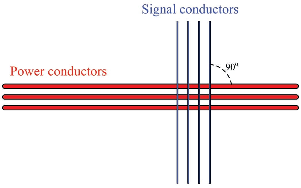
Perpendicular conductor orientation reduces both inter-conductor capacitance and mutual inductance by two mechanisms. Capacitance between conductors is reduced by means of minimizing overlapping area (\(A\)) resulting from the perpendicular crossing. Mutual inductance is reduced by decreasing the coupling coefficient (\(k\)) to nearly zero since the magnetic field generated perpendicular to the current-carrying wire will be parallel and not perpendicular to the “receiving” wire. Since the vector for induced voltage is perpendicular to the magnetic field (i.e. parallel with the current vector in the “primary” wire) there will be no voltage induced along the length of the “receiving” wire.
The problem of power-to-signal line coupling is most severe when the signal in question is analog rather than digital. In analog signaling, even the smallest amount of coupled “noise” corrupts the signal. A digital signal, by comparison, will become corrupted only if the coupled noise is so great that it pushes the signal level above or below a detection threshold it should not cross. This disparity is best described through illustration.
Two signals are shown here, coupled with equal amounts of noise voltage:

The peak-to-peak amplitude of the noise on the analog signal is almost 20% of the entire signal range (the distance between the lower- and upper-range values), representing a substantial degradation of signal integrity. Analog signals have infinite resolution, which means any change in signal amplitude has meaning. Therefore, any noise whatsoever introduced into an analog signal will be interpreted as variations in the quantity that signal is supposed to represent.
That same amount of noise imposed on a digital signal, however, causes no degradation of the signal except for one point in time where the signal attempts to reach a “low” state but fails to cross the threshold due to the noise. Other than that one incident represented in the pulse waveform, the rest of the signal is completely unaffected by the noise, because digital signals only have meaning above the “high” state threshold and below the “low” state threshold. Changes in signal voltage level caused by induced noise will not affect the meaning of digital data unless and until the amplitude of that noise becomes severe enough to prevent the signal’s crossing through a threshold (when it should cross), or causes the signal to cross a threshold (when it should not).
From what we have seen here, digital signals are far more tolerant of induced noise than analog signals, all other factors being equal. If ever you find yourself in a position where you must route a signal wire near AC power conductors, and you happen to have the choice whether it will be an analog signal (e.g. 4-20 mA, 0-10 V) or a digital signal (e.g. EIA/TIA-485, Ethernet), your best option is to choose the digital signal to coexist alongside the AC power wires.
Electric Field (Capacitive) De-Coupling
The fundamental principle invoked in shielding signal conductor(s) from external electric fields is that no substantial electric field can exist within a solid conductor. Electric fields exist due to imbalances of electric charge. If such an imbalance of charge ever were to exist within a conductor, charge carriers (typically electrons) in that conductor would quickly move to equalize the imbalance, thus eliminating the electric field. Another way of saying this is to state that electric fields only exist between points of different potential, and therefore cannot exist between equipotential points. Thus, electric flux lines may be found only in the dielectric (insulating media) between conductors, not within a solid conductor:
This also means electric flux lines cannot span the diameter of a hollow conductor:
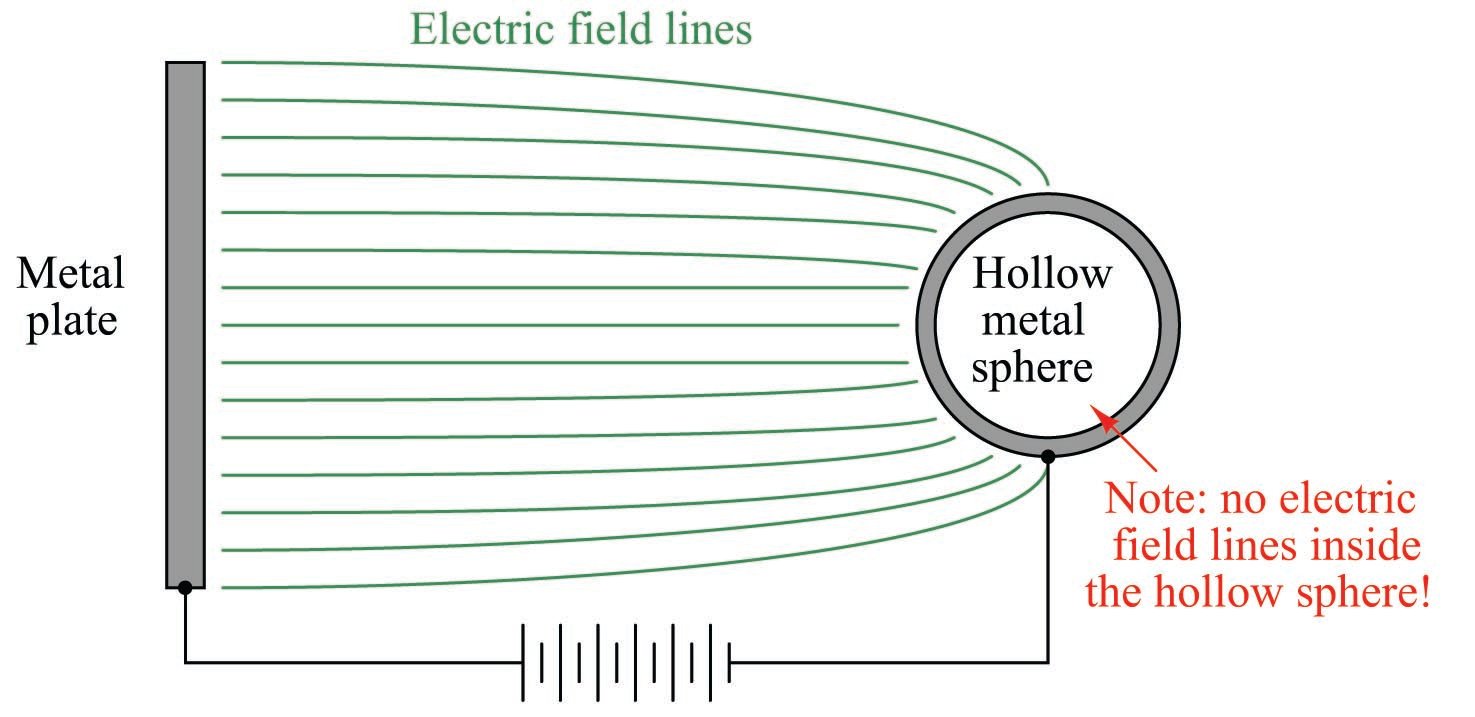
The electrical conductivity of the hollow sphere’s wall ensures that all points on the circumference of the sphere are equipotential to each other. This in turn prohibits the formation of any electric flux lines within the interior air space of the hollow sphere. Thus, all points within the hollow sphere are shielded from any electric fields originating outside of the sphere.
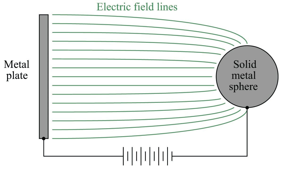
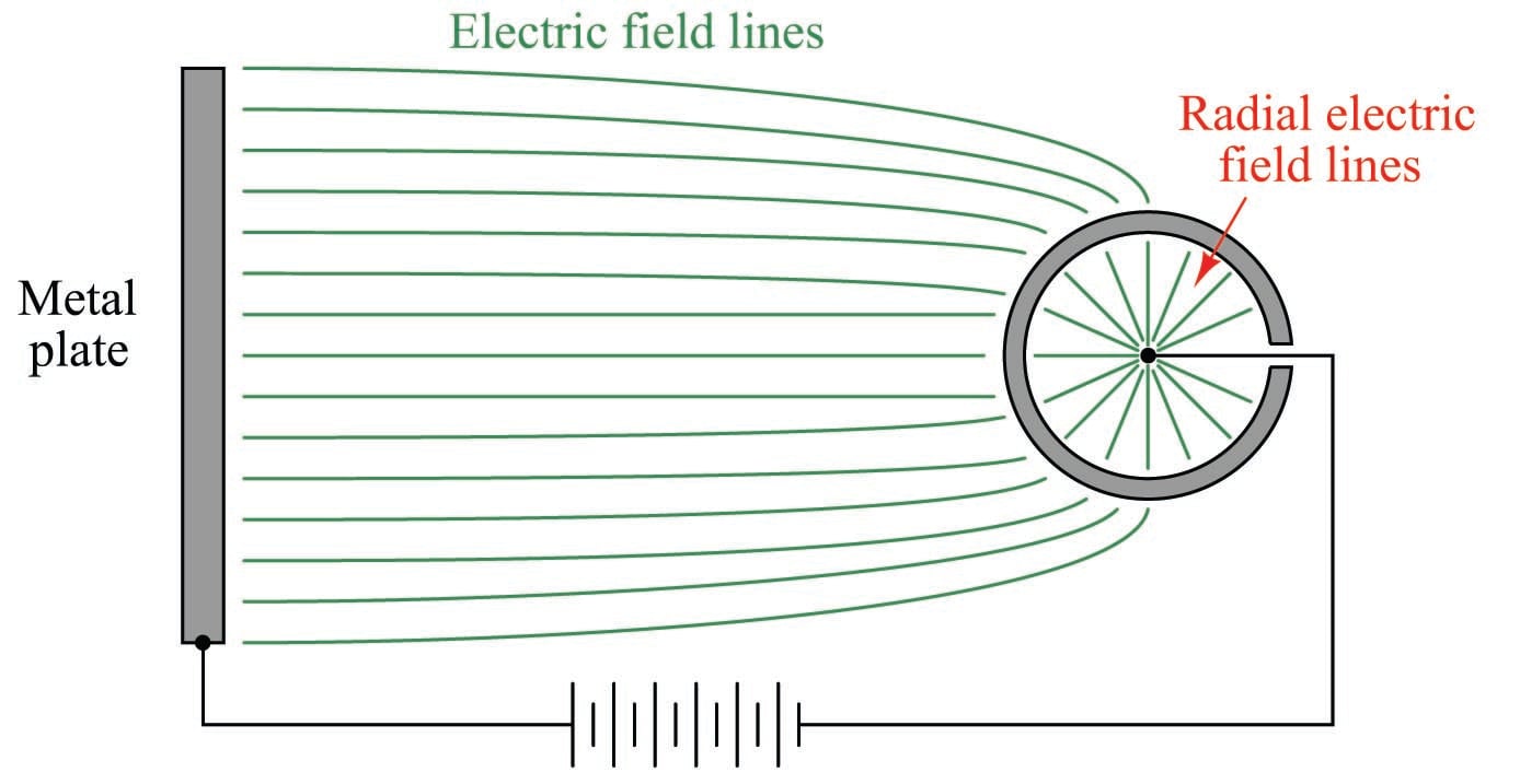
The only way to allow an external electric field to penetrate a hollow conductor from the outside is if that conductive shell is left “floating” with respect to another conductor placed within the shell. In this case the lines of electric flux do not exist between different points on the conductive sphere, but rather between the shell of the sphere and the conductor at the center of the sphere because those are the points between which a potential difference (voltage) exists. To illustrate:
However, if we make the hollow shell electrically common to the negative side of the high-voltage source, the flux lines inside the sphere vanish, since there is no potential difference between the internal conductor and the conductive shell:

If the conductor within the hollow sphere is elevated to a potential different from that of the high-voltage source’s negative terminal, electric flux lines will once again exist inside the sphere, but they will reflect this second potential and not the potential of the original high-voltage source. In other words, an electric field will exist inside the hollow sphere, but it will be completely isolated from the electric field outside the sphere. Once again, the conductor inside is shielded from external electrostatic interference:

If conductors located inside the hollow shell are thus shielded from external electric fields, it means there cannot exist any capacitance between external conductors and internal (shielded) conductors. If there is no capacitance between conductors, there will never be capacitive coupling of signals between those conductors, which is what we want for industrial signal cables to protect those signals from external interference.
All this discussion of hollow metal spheres is just an introduction to a discussion of shielded cable, where electrical cables are constructed with a conductive metal foil wrapping or conductive metal braid surrounding the interior conductors. Thus, the foil or braid creates a conductive tube which may be connected to ground potential (the “common” point between external and internal voltage sources) to prevent capacitive coupling between any external voltage sources and the conductors within the cable:
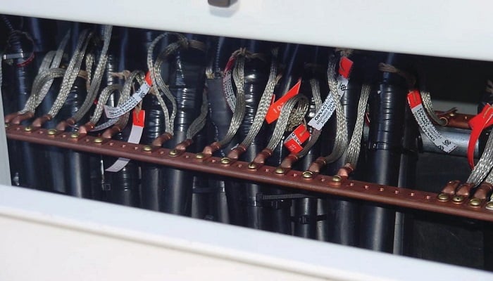
The following photograph shows a set of signal cables with braided shield conductors all connected to a common copper “ground bus.” This particular application happens to be in the control panel of a 500 kV circuit breaker, located at a large electrical power substation where strong electric fields abound:
This next photograph shows a four-conductor USB cable stripped at one end, revealing a metal-foil shield as well as silver-colored wire strands in direct contact with the foil, all wrapped around the four colored power and signal conductors:
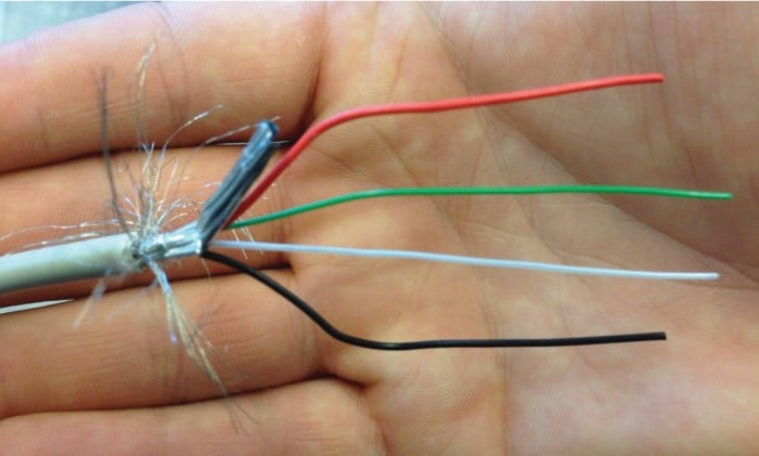
At the terminating end, we typically twist the loose shield conductor strands together to form a wire which is then attached to a ground point to fix the cable’s shield at Earth potential.
It is very important to ground only one end of a cable’s shield, or else you will create the possibility for a ground loop: a path for current to flow through the cable’s shield resulting from differences in Earth potential at the cable ends. Not only can ground loops induce noise in a cable’s conductor(s), but in severe cases it can even overheat the cable and thus present a fire hazard:

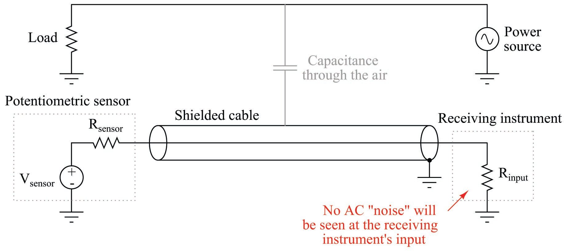
An important characteristic of capacitively-coupled noise voltage is that it is common-mode in nature: the noise appears equally on every conductor within a cable because those conductors lie so close to each other (i.e. because the amount of capacitance existing between each conductor and the noise source is the same). One way we may exploit this characteristic in order to help escape the unwanted effects of capacitive coupling is to use differential signaling. Instead of referencing our signal voltage to ground, we let the signal voltage “float.” The following schematic diagram illustrates how this works:
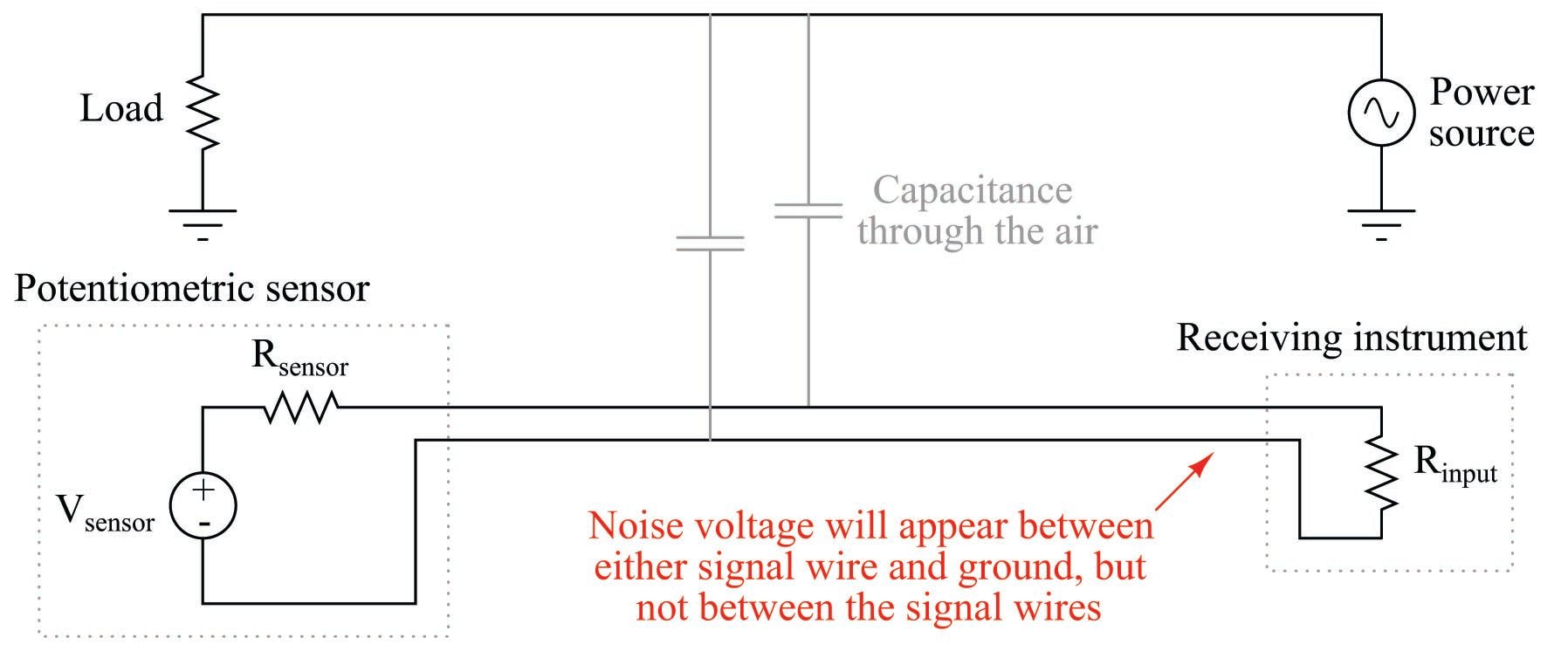
The lack of a ground connection in the DC signal circuit prevents capacitive coupling with the AC voltage from corrupting the measurement signal “seen” by the instrument. Noise voltage will still appear between either signal wire and ground as a common-mode voltage, but noise voltage will not appear between the two signal wires where our signal of interest exists. In other words, we side-step the problem of common-mode noise voltage by making common-mode voltage irrelevant to the sensor and to the signal receiver.
Some industrial data communications standards, such as RS-485, use this technique to minimize the corrupting effects of electrical noise.
Magnetic Field (Inductive) De-Coupling
Magnetic fields, unlike electric fields, are exceedingly difficult to completely shield. Magnetic flux lines do not terminate, but rather loop. Thus, one cannot “stop” a magnetic field, only redirect its path. A common method for magnetically shielding a sensitive instrument is to encapsulate it in an enclosure made of some material having an extremely high magnetic permeability (\(\mu\)): a shell offering much easier passage of magnetic flux lines than air. A material often used for this application is mu-metal, or \(\mu\)-metal, so named for its excellent magnetic permeability:

This sort of shielding is impractical for protecting signal cables from inductive coupling, as mu-metal is rather expensive and must be layered relatively thick in order to provide a sufficiently low-reluctance path to shunt most of the external magnetic flux lines.
The most practical method of granting magnetic field immunity to a signal cable follows the differential signaling method discussed in the electric field de-coupling section, with a twist (literally). If we twist a pair of wires rather than allow them to lie along parallel straight lines, the effects of electromagnetic induction are vastly minimized.
The reason this works is best illustrated by drawing a differential signal circuit with two thick wires, drawn first with no twist at all. Suppose the magnetic field shown here (with three flux lines entering the wire loop) happens to be increasing in strength at the moment in time captured by the illustration:

According to Lenz’s Law, a current will be induced in the wire loop in such a polarity as to oppose the increase in external field strength. In other words, the induced current tries to “fight” the imposed field to maintain zero net change. According to the right-hand rule of electromagnetism (tracing current in conventional flow notation), the induced current must travel in a counter-clockwise direction as viewed from above the wire loop in order to generate a magnetic field opposing the rise of the external magnetic field. This induced current works against the DC current produced by the sensor, detracting from the signal received at the instrument.
When the external magnetic field strength diminishes, then builds in the opposite direction, the induced current will reverse. Thus, as the AC magnetic field oscillates, the induced current will also oscillate in the circuit, causing AC “noise” voltage to appear at the measuring instrument. This is precisely the effect we wish to mitigate.
Immediately we see a remarkable difference between noise voltage induced by a magnetic field versus noise voltage induced by an electric field: whereas capacitively-coupled noise was always common-mode, here we see inductively-coupled noise as differential.
If we twist the wires so as to create a series of loops instead of one large loop, we will see that the inductive effects of the external magnetic field tend to cancel:
[Twisted wire pair physics]

Not all the lines of flux go through the same loop. Each loop represents a reversal of direction for current in the instrument signal circuit, and so the direction of magnetically-induced current in one loop directly opposes the direction of magnetically-induced current in the next. So long as the loops are sufficient in number and spaced close together, the net effect will be complete and total opposition between all induced currents, with the result of no net induced current and therefore no AC “noise” voltage appearing at the instrument.
In order to enjoy the benefits of magnetic and electric field rejection, instrument cables are generally manufactured as twisted, shielded pairs. The twists guard against magnetic (inductive) interference, while the grounded shield guards against electric (capacitive) interference. If multiple wire pairs are twisted within the same cable, the twist rates of each pair may be made different so as to avoid magnetic coupling from pair to pair.
High-Frequency Signal Cables
Electronic signals used in traditional instrumentation circuits are either DC or low-frequency AC in nature. Measurement and control values are represented in analog form by these signals, usually by the magnitude of the electronic signal (how many volts, how many milliamps, etc.). Modern electronic instruments, however, often communicate process and control data in digital rather than analog form. This digital data takes the form of high-frequency voltage and/or current pulses along the instrument conductors. The most capable fieldbus instruments do away with analog signaling entirely, communicating all data in digital form at relatively high speeds.
If the time period of a voltage or current pulse is less than the time required for the signal to travel down the length of the cable (at nearly the speed of light!), very interesting effects may occur. When a pulse propagates down a two-wire cable and reaches the end of that cable, the energy contained by that pulse must be absorbed by the receiving circuit or else be reflected back down the cable. To be honest, this happens in all circuits no matter how long or brief the pulses may be, but the effects of a “reflected” pulse only become apparent when the pulse time is short compared to the signal propagation time. In such short-pulse applications, it is customary to refer to the cable as a transmission line, and to regard it as a circuit component with its own characteristics (namely, a continuous impedance as “seen” by the traveling pulse).
This problem has a familiar analogy: an “echo” in a room. If you step into a large room with hard wall, floor, and ceiling surfaces, you will immediately notice echoes resulting from any sound you make. Holding a conversation in such a room can be quite difficult, as the echoed sounds superimpose upon the most recently-spoken sounds, making it difficult to discern what is being said. The larger the room, the longer the echo delay, and the greater the conversational confusion.
Echoes happen in small rooms, too, but they are generally too short to be of any concern. If the reflected sound(s) return quickly enough after being spoken, the time delay between the spoken (incident) sound and the echo (reflected) sound will be too short to notice, and conversation will proceed unhindered.
We may address the “echo” problem in two entirely different ways. One way is to eliminate the echoes entirely by adding sound-deadening coverings (carpet, acoustic ceiling tiles) and/or objects (sofas, chairs, pillows) to the room. Another way to address the problem of echoes interrupting a conversation is to slow down the rate of speech. If the words are spoken slowly enough, the time delay of the echoes will be relatively short compared to the period of each spoken sound, and conversation may proceed without interference (albeit at a reduced speed).
Both the problem of and the solutions for reflected signals in electrical cables follow the same patterns as the problem of and solutions for sonic echoes in a hard-surfaced room. If an electronic circuit receiving pulses sent along a cable receives both the incident pulse and an echo (reflected pulse) with a significant time delay separating those two pulses, the digital “conversation” will be impeded in the same manner that a verbal conversation between two or more people is impeded by echoes in a room. We may address this problem either by eliminating the reflected pulses entirely (by ensuring all the pulse energy is absorbed by an appropriate load placed at the cable’s end) or by slowing down the data transfer rate (i.e. longer pulses, lower frequencies) so that the reflected and incident pulse signals virtually overlap one another at the receiver.
High-speed “fieldbus” instrument networks apply the former solution (eliminate reflections) while the legacy HART instrument signal standard apply the latter (slow data rate). Reflections are eliminated in high-speed data networks by ensuring the two furthest cable ends are both “terminated” by a resistance value of the proper size (matching the characteristic impedance of the cable). The designers of the HART analog-digital hybrid standard chose to use slow data rates instead, so their instruments would function adequately on legacy signal cables where the characteristic impedance is not standardized.
The potential for reflected pulses in high-speed fieldbus cabling is a cause for concern among instrument technicians, because it represents a new phenomenon capable of creating faults in an instrument system. No longer is it sufficient to have tight connections, clean wire ends, good insulation, and proper shielding for a signal cable to faithfully convey a 4-20 mA DC instrument signal from one device to another. Now the technician must ensure proper termination and the absence of any discontinuities (sharp bends or crimps) along the cable’s entire length, in addition to all the traditional criteria, in order to faithfully convey a digital fieldbus signal from one device to another.
Signal reflection problems may be investigated using a diagnostic instrument known as a time-domain reflectometer, or TDR. These devices are a combination of pulse generator and digital-storage oscilloscope, generating brief electrical pulses and analyzing the returned (echoed) signals at one end of a cable. If a TDR is used to record the pulse “signature” of a newly-installed cable, that data may be compared to future TDR measurements on the same cable to detect cable degradation or wiring changes.

Really interesting article