 Facebook
 Google
 GitHub
 Linkedin
Fiber Optic Data Communication
Light has long been used as a long-range signaling medium. While communication by light through open air is still possible using modern technology, it is far more practical in most cases to channel the light signals through a special strand of optically transparent material called an optical fiber. When packaged in a protective sheath, it is known as a fiber optic cable.
The transmission of light through a “light pipe” was demonstrated as early as 1842 by Daniel Colladon and Jacques Babinet in Paris, using a running stream of water to guide a beam of light. Many modern houses in the United States are equipped with light-pipes directing natural sunlight into rooms for illumination, without the use of “skylight” ceiling windows. Modern fiber optic cables apply similar optical principles to very small-diameter fibers of transparent material (usually ultra-pure glass), able to convey optical energy and optically-encoded information.
Fiber optic data communication
Simply put, an optical fiber is a “pipe” through which light flows. This is, of course, merely an analogy for how an optical fiber works, but it conveys the basic idea. The interface between a piece of electronic equipment and an optical fiber consists of an optical source (typically an LED or a semiconductor laser) to generate light signals from electrical signals, and an optical detector (typically a photodiode or phototransistor) to generate electrical signals from received light signals.
The predominant use of optical fiber in modern industry is as a data communication medium between digital electronic devices, replacing copper-wire signal and network cabling. An illustration showing two digital electronic devices communicating over a pair of optical fibers appears here, each fiber “conducting” pulses of light (representing serial digital data) from an LED source to a photodiode detector:

The following photograph shows a serial converter (the black rectangular plastic box with a blue label) used to convert optical data pulses entering and exiting through orange-jacketed optical cables (on the left) into EIA/TIA-232 compliant electrical signals through a DB-9 connector (on the right) and vice-versa, allowing the electronic serial data device on the right-hand side of the photograph to communicate via fiber optic cabling:

Note how the two optical fiber ports on the converter body are labeled “R” and “T” for Receive and Transmit, respectively. Serial devices with built-in electronic/optical converters will similarly label their optical ports.
For this device, connection to each of the optical fibers is made using an “ST” style connector, with a quarter-turn locking ring holding each one in place (much like the quarter-turn barrel body of a “BNC” style electrical connector). The next photograph shows a pair of optical fibers terminated with ST-style connectors. White plastic caps cover the connector tips, keeping the glass fiber ends protected from dust and abrasion:

As a data pathway, optical fiber enjoys certain advantages over electrical cable, including:
- Much greater bandwidth (data-carrying capacity), estimated to be in the terahertz range
- Much less equivalent signal power loss per unit cable length (less than 1 dB per kilometer compared with 25 dB per kilometer for coaxial cable)
- Complete immunity to external “noise” sources
- No radiation of energy or data from the cable, thus will not create interference nor be liable to eavesdropping
- No electrical conductivity, allowing safe routing of cables near high voltage conductors
- Total galvanic isolation (i.e. no electrically conductive connection) between data devices, allowing operation at different electrical potentials
- Safe for use in areas with explosive vapors, dust, and/or fibers
These advantages deserve some elaboration. The superior bandwidth of fiber-optic cable is so dramatic that the present-day (2015) limitation on data transfer rates for most fiber-optic installations is the electronic devices at each end, and not the optical fiber itself! This, combined with the low inherent power loss of optical fiber, makes it an ideal medium for long-range data communication such as telephone and internet. Thousands of miles of optical fiber cable have been buried in underground trenches, laid down on sea floors, strung as overhead lines, and used as “patch” cables in room-scale applications since the advent of affordable optical cabling in the 1980’s. The “tech boom” of the 1990’s saw an impressive amount of trans-continental and inter-continental optical fiber installation, paving the way for the global expansion of internet services into the 21st century. The limitations of electronics at each end of these long fibers means we have not yet begun to tap their full data-carrying capacity, either. Conveying data in photonic – as opposed to electronic – form means there is absolutely no such thing as capacitive or inductive coupling with external systems as there is with conductive wire cable, which not only means optical fiber communication is immune to external interference but also that the optical signals cannot create interference for any other system. Since optical fibers are customarily manufactured from glass which is electrically non-conductive, it is possible to route optical fibers alongside high-voltage power lines, and also connecting together devices at vastly different electrical potentials from each other, with no risk of bridging those differing potentials. Finally, the low power levels associated with optical fiber signals also makes this technology completely safe in areas where explosive compounds in the atmosphere might otherwise be ignited by faults in electrical communications cable.
Optical fibers also suffer from some unique limitations when compared against electrical cable, including:
- Need to avoid tight bend radii for optical cables
- Connections need to be extremely clean
- Specialized tools and skills necessary for installation and maintenance
- Expensive testing equipment
While electrical “transmission line” signal cables must also avoid sharp bends and other discontinuities caused by cramped installations, this need is especially pronounced for optical fiber (for reasons which will be explained later in this section). Since fiber-to-fiber connections consist of glass pressed against glass, the presence of even microscopic contaminants such as dust particles may damage fiber optic connectors if they aren’t cleaned prior to insertion. Cutting, preparing, and terminating optical fiber cables requires its own set of specialized tools and skills, and is not without unique hazards. Lastly, the test equipment necessary to check the integrity of an optical pathway is similarly specialized and typically quite expensive.
Fiber optic sensing applications
Optical fibers find applications beyond electronic data cable replacement, though, which means they will be a growing presence in the field of industrial instrumentation above and beyond their use as serial data communication cables. Some industrial process transmitters use optical fibers to send and receive light between the transmitter electronics and an optically-based primary sensing element. This may be as simple as a non-contact proximity switch using light to sense the presence of an object within a gap between the two fibers’ ends, or as sophisticated as a chemical analyzer relying on the absorption of specific light wavelengths to detect the presence of a chemical substance in a solution.
Turbine flowmeter sensing
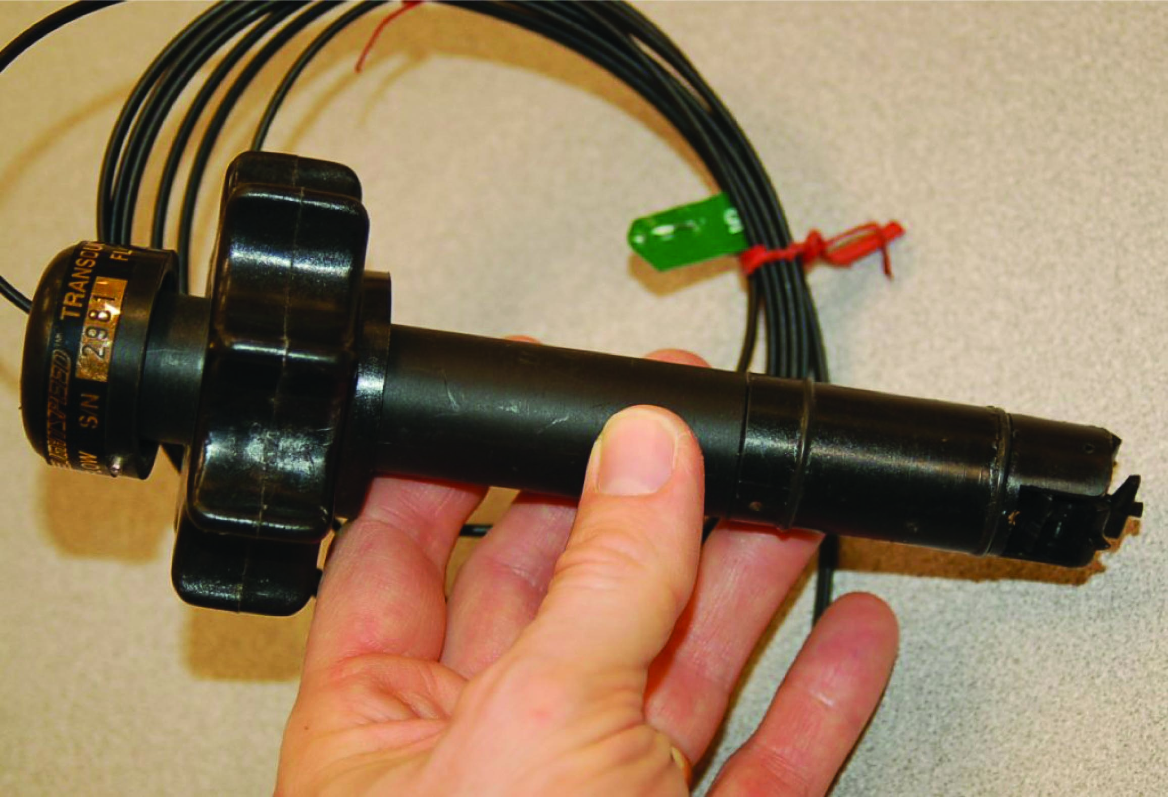
One example of a specialized application for optical fibers is shown in this photograph of a paddlewheel-style liquid flowmeter using a pair of optical fibers to convey light to and from the paddlewheel assembly, where the spinning paddlewheel serves to “chop” the light beam and thereby represent liquid flow rate as a frequency of pulsing light:
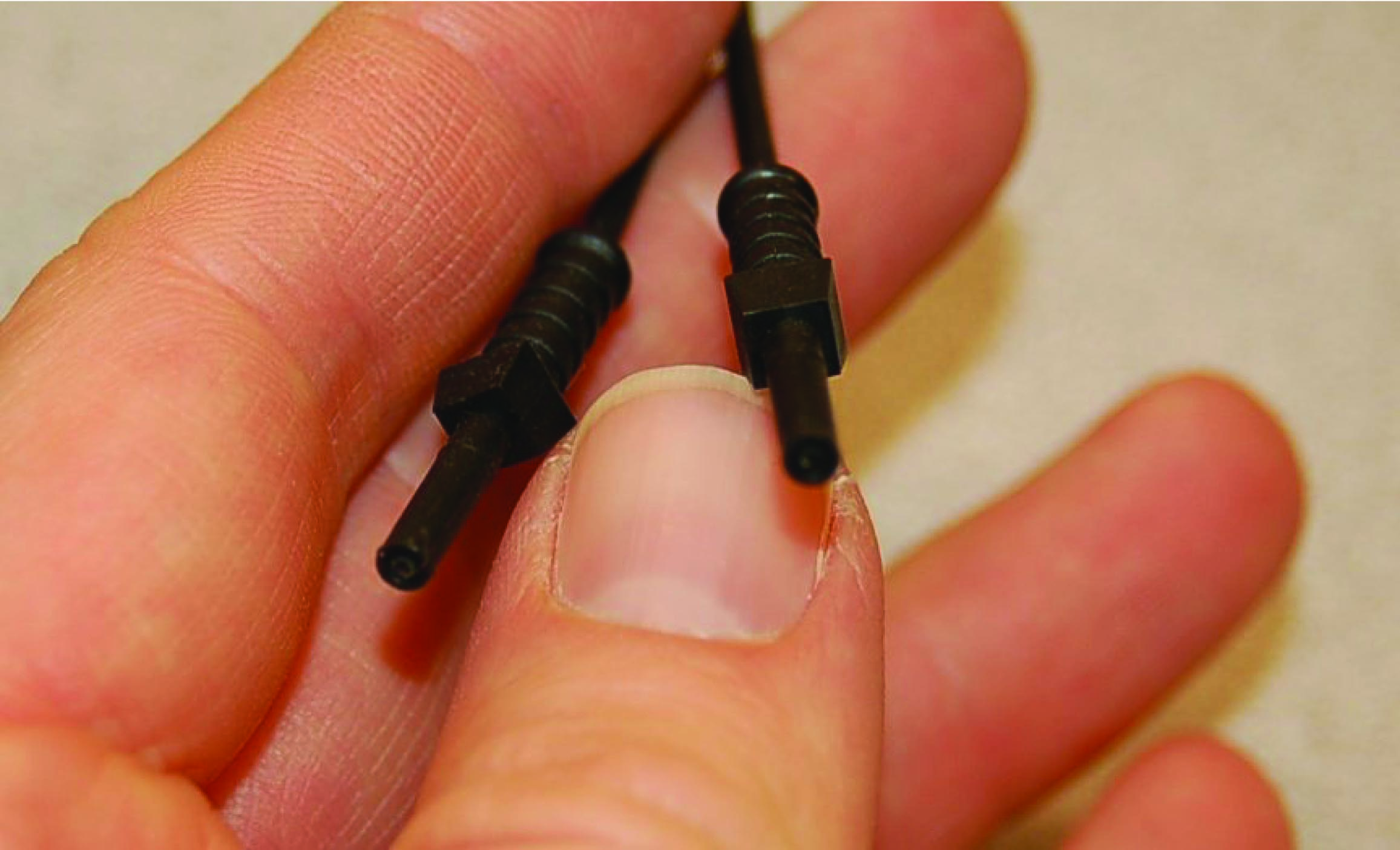
An end-view of the two optical fibers is shown in the next photograph. When installed as a working system, these two fibers will plug into a flow transmitter device sending a continuous beam of light through one fiber and sensing the pulsed light signal coming back from the paddlewheel through the other fiber:
Fabry-Perot interferometry temperature measurement
Another example of a specialized application for optical fibers is measurement of high temperatures using the Fabry-Perot interferometry method. This technology utilizes a small, thin disk of sapphire as a temperature sensor. The thickness of this disk as well as the speed of light through the sapphire are both temperature-dependent, which means a photon261 of light shot at the face of the disk will reflect off the back face of the disk and return to the source at different times depending on the temperature of the disk. In a Fabry-Perot interferometer instrument, the “optical thickness” of the sapphire disk is measured by sending a continuous beam of white light to the disk and receiving the reflected light from the disk through a single optical fiber, the optical interference resulting from the incident and reflected light beams representing the disk’s temperature. This novel method of temperature measurement shows promise for certain challenging industrial process applications such as high-temperature measurement inside slagging coal gasifiers used to efficiently extract energy and chemical feedstocks from coal:

Dissolved oxygen measurement
Yet another example of a specialized application for optical fibers is the measurement of dissolved oxygen in aqueous solutions using the dynamic luminescence quenching or fluorescence quenching method. This technology uses a thin layer of solid material containing molecules known to fluoresce with red light when exposed to visible light of a shorter wavelength (typically green or blue). Oxygen molecules present in the liquid solution tend to bond with the fluorescing molecules in the sensor and inhibit that fluorescence, thus providing a means of measuring oxygen concentration near the sensor: the less O\(_{2}\) dissolved in solution, the stronger the fluorescence (i.e. more red light received, for a longer duration); the more O\(_{2}\), the less fluorescence. Optical fibers convey both the incident (green or blue) and returned (red) light between the wet sensing element and the interpreting electronics.

In both the Fabry-Perot interferometry and the fluorescence quenching sensors, the function of the fiber optic cable is to physically separate the sensing element from the sophisticated and fragile electronic transmitter needed to interpret the optical signal as a process variable measurement.
Arc flash detection
There is at least one application where the optical fiber itself is the sensing element: arc flash detection within high-voltage switchgear cabinets. “Arc flash” is the phenomenon of intense heat and light developed at a high-current electrical arc, especially a phase-to-phase arc between electric power conductors where there is little circuit resistance to limit fault current. High-voltage switchgear is constructed in such a way as to extinguish the arc normally developed at the contacts during each “opening” cycle, but certain faults within a piece of switchgear may inhibit this extinguishing function. In such cases the potential for equipment damage and threat to human health and life is severe.
If a bare (unjacketed) optical fiber is properly arranged within a piece of switchgear, an arc flash event will inject enough light through the fiber that some of it will be detected at the far end where it meets a light-sensitive receiver. Since the fiber itself is not electrically conductive, there is no risk of conducting a high-voltage arc back to this receiver. The receiver, meanwhile, serves the purpose of commanding any “upstream” switchgear to trip open in the event of a detected arc fault. The early detection of arc flash by optical means rather than the time-delayed detection of the same fault by overcurrent or current-imbalance detection results in much faster clearing of the faulted switchgear from the power grid, both limiting equipment damage and limiting the potential for injury or death.
Fiber optic cable construction
Communication-grade optical fibers are manufactured from fused silica (SiO\(_{2}\)) glass of exceptional purity. A single strand of optical fiber made from this glass called the “core” serves as a waveguide for the light. The core is surrounded by another layer of glass called the “cladding” which has a different index of refraction necessary to “channel” the majority of the optical energy through the core and inhibit “leakage” of optical power from the cable. Additional layers of plastic and other materials around the core/cladding center provide coloring (for fiber identification in multi-fiber cables), protection against abrasion, and tensile strength so the cable will not suffer damage when pulled through conduit.
The purpose of building a fiber optic cable with a core and a cladding having different refractive indices (i.e. different speeds of light) is to exploit a phenomenon called total internal reflection, whereby rays of light reflect off the interface between core and cladding to prevent its unintentional escape from the core at any point along the length of the fiber.
When light crosses an interface between two materials having different speeds, the light beam will become refracted as a function of those two speeds as described by Snell’s Law:

Snell’s Law relates the sine of the incident angle to the sine of the refracted angle as a ratio to each material’s speed of light, the material possessing the greatest speed of light (i.e. the lowest refractive index value) exhibiting the greatest angle as measured from perpendicular to the interface:
\[{{\sin \theta_1} \over v_1} = {{\sin \theta_2} \over v_2}\]
According to Snell’s Law, there will be a critical angle at which the incident light ray will refract to being parallel to the interface. Beyond this critical angle, the light ray ideally reflects off the interface and never enters the second material at all. This is the condition of total internal reflection, and it is what we desire in an optical fiber where the core is the first material and the cladding is the second material:


Both the core and cladding of an optical fiber are manufactured from the same base material of ultra-pure fused silica, but “doped” with specific impurities designed to alter the refractive index of each one (raising the refractive index of the core to decrease its optical velocity and lowering the refractive index of the cladding to increase its optical velocity).
The diameter of core and cladding vary with the type of optical fiber, but several standard sizes have emerged in the industry, each one specified by the diameter of the core followed by the diameter of the cladding expressed in microns (millionths of a meter). A common optical fiber standard in the United States is 62.5/125 (62.5 micron core diameter, 125 micron cladding diameter), and 50/125 in Europe. Some less common standard core/cladding diameters include 85/125 and 100/140.
To give some perspective on the physical size of an optical fiber core, the following photograph shows the end-view of an “ST” style fiber optic connector for a 50/125 micron cable, held by my hand. A green LED light source is shining into the other end of this cable, the tiny green dot visible at the center of the ST connector revealing the diameter of the 50 micron core:

Several other layers of material must be placed over the core and cladding to form a rugged optical fiber. A plastic jacket with a typical diameter of 250 microns (0.25 mm) covers the cladding, and provides a base for color-coding the fiber. This three-layer construction of core, cladding, and jacket is known in the industry as Primary Coated Optical Fiber, or PCOF.
PCOF is still too fragile for end-user applications, and so another layer of plastic is typically added (900 microns in diameter) to make the fiber Secondary Coated Optical Fiber, or SCOF. When wrapped with fiberglass or Kevlar fibers around the secondary jacket for tensile strength, and a protective PVC plastic outer layer to protect against abrasion, the cable becomes suitable for indoor use. Cables suitable for outdoor, direct burial, and undersea applications usually take the form of groups of PCOF fibers packaged within an extremely rugged encasement with metal strands for tensile strength. Sometimes a gel material helps cushion the fibers from each other within the confines of the cable sheath.
Multi-mode and single-mode optical fibers
In any sort of waveguide – optical, electrical, or even acoustical (sound) – the signal energy may be able to propagate down the waveguide in different orientations. This is true for optical fibers where the core diameter is relatively large compared to the wavelength of the light: there will be many alternative pathways for light to travel along the length of a fiber’s core. Optical fibers with core diameters of 50 microns or more are referred to as multi-mode fibers, because multiple independent pathways, or “modes”, of light are possible within the core’s width.
If an optical fiber’s core is manufactured to be small enough, relative to the wavelength of the light used, the fiber will only support one “mode” or pathway down its core. Such fiber is called single-mode. Single-mode fiber cores typically range from 4 to 10 microns in diameter, with 8 micron being typical.
The purpose of single-mode optical fiber is to avoid a problem called modal dispersion. When multiple “modes” of light propagate down the length of an optical fiber, they don’t all have the same length. That is to say, some modes actually take a straighter (and more direct) path down the fiber’s core than others. The reason this is a problem is that this phenomenon corrupts the integrity of high-speed (i.e. short-period) pulses. An exaggerated illustration of this problem appears here, showing the relative path lengths of three different light rays, each one entering the fiber core at a slightly different angle. The light ray closest to parallel with the core’s centerline finds the shortest “mode” to the fiber’s end, and arrives in the least amount of time:

With different “modes” of light arriving at different times from the same incident pulse, the received light pulse at the exiting end of the fiber will no longer possess a crisp “square-wave” shape. Instead, the pulse will be “smeared” over time, occupying a larger time span. This poses a bandwidth limit on the fiber, as there will be some maximum pulse frequency at which adjacent pulses will begin to merge together and become indistinguishable. The longer the length of optical fiber, the more pronounced this dispersion will be. This problem is most evident in applications where the fiber length is very long (hundreds of miles) and the data rate is very high (hundreds of megahertz). Thus, it is a significant problem for long-distance data trunk cables such as those used for transcontinental and intercontinental internet traffic.
Single-mode optical fiber completely averts this problem by eliminating multiple modes within the fiber core. When there is only one mode (pathway) for light to travel, there will be exactly one distance for light to travel from one end of the fiber to the other. Therefore, all portions of the incident light pulse experience the same travel time, and the light pulse arrives at the far end of the cable suffering no modal dispersion:

As you can imagine, single-mode fiber is more challenging to splice than multi-mode fiber, as the smaller core diameter provides less room for alignment error.
A compromise solution to the problem of modal dispersion in multi-mode fibers is to manufacture the core glass with a graded index of refraction rather than a homogeneous index of refraction. This means the concentration of doping material in the glass varies from the center of the core to the outer diameter of the core where it interfaces with the cladding. The result of this graded dispersion is that modes traveling closest to the core’s centerline will experience a slower speed of light (i.e. greater index of refraction) than modes near the edge of the core, which means the difference in travel time from one mode to the next will be less pronounced than within normal “step-index” fibers. Of course, this also means graded-index optical fiber is more costly to manufacture than step-index optical fiber.
Fiber optic cable connectors, routing, and safety
One of the most popular styles of single-fiber connector is the so-called “ST” style, which uses a quarter-turn locking barrel to secure the connector into its matching socket:
Communication patch cables such as the one shown above come in pairs of fibers, one for receiving and one for transmitting. Note how the plastic strain-relief grips between the metal barrel of each connector and each orange-jacketed cable are color-coded (one white, one black) for easy identification at each end of the cable.
An older style of connector based on the type used to connect small coaxial cables together is the “SMA” style, which used a threaded barrel to lock each fiber in place. The SMA-style connectors were very secure, but laborious to engage and disengage due to the fine pitch of the barrel’s threads and the subsequent need to turn the barrel multiple rotations (versus one-quarter turn of the barrel for an ST connector).
Given that communication patch cables typically have two fibers (one for each direction of data flow), connector styles have emerged to accommodate fiber pairs. One such style is the so-called “SC” connector, with a pair of side-by-side plugs accommodating twin optical fibers.
Terminating a bare cable of fibers with individual connectors is a time-consuming process, requiring the technician to unbundle the individual fibers, strip the jacketing off of each one to reveal the core and cladding, cleave each glass fiber to give it a flat end, and finally insert and secure each fiber into its respective connector. Typical fiber connectors use either a “hot-melt” or a chemical epoxy system of attachment, where the glue adheres to the strain-relief fibers of the cable for tensile strength, while the central glass fiber protrudes through a small hole in the center of the connector tip. This protruding glass fiber must be carefully cut and polished to produce a flat end suitable for engagement with another optical fiber aligned to its center.
Optical fibers may be spliced mid-way in a cable run, although this practice should be avoided whenever possible. If the fibers are multi-mode, the splicing may be done using “butt” connectors but the power losses may be unacceptable. Alternatively, stripped fibers may be inserted into both ends of a small-diameter tube filled with gel having the same index of refraction as the core glass, to “conduct” light with as little loss as possible from one fiber core to the other.
A very good technique often applied to single-mode fiber is that of fusion splicing, where two single-mode fiber ends are literally melted together using an electric arc so that they form one seamless glass fiber. The alignment of fibers prior to fusion is done under the view of a microscope, and often with the aid of a light source on one end and an optical power meter on the other end to give a quantitative measurement of alignment accuracy. When the two fibers are aligned as close as possible, the electric arc is fired to melt the two fibers together, creating a single fiber. Fusion splicing is the method of choice for long-distance runs of single-mode fiber, where low power loss and high integrity of the splice are paramount factors.
When laying optical fiber in wire trays, pulling through rigid conduit, or arranging it in connection panels, an important physical consideration is to maintain a minimum bend radius at all points along the fiber’s length. This is important because sharp bends will cause light to “leak” out of the fiber core and into the cladding where it may then escape the cable altogether. A sharp bend in an optical fiber will cause the angle between the light ray and the core/cladding interface to reach the critical point where total internal reflection no longer occurs:

The light leakage from an optical fiber may be dramatic if the bend is sharp enough. On an indoor cable, using visible laser light, you can actually see the light “leak” through to the PVC outer coating on the outside of the cable!
Junction boxes and connection panels where excess lengths of fiber optic cabling may be coiled will typically provide plastic forms over which those loops of cable may be bent, the radius of that plastic form exceeding the manufacturer’s specification for minimum bend radius.
A common way in which the minimum bend radius requirement is violated is when a cable tie is used to anchor a fiber optic cable to some sturdy surface such as a wiretray or a cabinet post. The sharp bend created by the tension of a tightened cable tie on the fiber optic cable will easily exceed the minimum bend radius for that cable, creating light leakage and subsequent performance problems. Therefore, a good installation practice for fiber optic cables is to always leave cable ties loose enough that they do not tightly grip the cable.
There are multiple safety concerns when working with optical fibers, both when installing them and when doing maintenance-type work. Installation hazards center around dangers of the glass fiber itself, while maintenance hazards center around the light sources used to “power” the optical fibers.
Installation of fiber optic cable requires that individual glass fibers be separated from each other in a multi-fiber cable and each one terminated with a connector, and this requires at some point that the technician strip each fiber down to its glass core and cladding. Both the core and the cladding are extremely small in diameter, and are made of ultra-pure glass. If a piece of core/cladding breaks off the fiber and penetrates the skin, the resulting “sliver” will be nearly invisible due to its exceptional transparency. Its outer surface is also very smooth, making extraction difficult. Unextracted pieces of an optical fiber, if left in the body, can actually migrate through the victim’s flesh and become buried even deeper to the point where they can cause serious health problems.
Technicians working with optical fiber typically lay a length of adhesive tape, sticky-side up, on whatever workbench or table they are using to prepare the cable, as a tool to catch any loose fiber ends they cut off. At the conclusion of the job, this length of tape is carefully rolled up and then disposed of in the same manner that “sharps” may be disposed of in a medical environment.
Maintenance technicians working with functioning fiber optic systems need to be careful when disconnecting “hot” fibers, due to the intensity of the light used in some systems. This is especially true of long-distance telecommunication fibers using laser sources rather than regular LEDs, which may have power levels reaching a half watt or so. One-half of a watt doesn’t sound like very much power, but when you consider this power level is concentrated over a circular area with a diameter less than 10 microns (for single-mode fiber), the watt-per-square-meter value is actually large enough to cause significant temperature increases wherever the light beam happens to fall. In fact, you can actually damage a fiber-optic connector on such a system by disconnecting the fiber with the fiber “powered”, the laser light being intense enough to burn and pit the aluminum ferrule of the connector!
Even standard LED light sources may pose a hazard if a technician directly views the end of the cable with his or her eyes, due to the focused nature of the light beam. The retina of your eye is extremely sensitive to light, and may easily be damaged by viewing such an intensely focused beam coming out of an optical fiber, where the entire LED’s light output is channeled into a core just a fraction of a millimeter in diameter. The optical hazard is even greater when infra-red light sources are used, because there is no visible indication of the light’s presence. A technician won’t even be able to see the light coming out, yet it could still be intense enough to damage their retina(s).
Laser-sourced fibers should never be unplugged from the equipment. One should treat a laser-sourced fiber with the same respect as a “live” electrical circuit, and use the same lockout/tagout procedures to ensure personnel safety. In systems using visible light wavelengths, a safe way to view the light coming out the end of an optical fiber is to point the fiber end at a piece of paper and look for the colored dot falling on the paper. The paper’s rough surface scatters the light so that it is no longer a focused beam.
The only time it is truly safe to view the end of an optical fiber to check for light is when the light source is something diffuse such as natural sunlight or a flashlight. It is common for technicians to use a flashlight to identify fibers from one end of a multi-fiber cable to the other, one technician shining the flashlight at the end of one fiber while another technician views all the fibers at the other end of the cable to see which one is lit.
Some optical communications equipment come equipped with a feature called an Open Fiber Control (OFC) safety system, which turns off all light sources on a channel whenever an interruption of light is detected at the receiver port. Since most duplex (two-way) optical fiber channels consist of two fibers (one for each direction of light), a break in any one fiber will darken one receiver, which then commands the transmitter port on that equipment to darken as well to prevent anyone getting injured from the light. It also completely disrupts communication in that channel, requiring a re-initialization of the channel after the fiber is plugged back in.
Fiber optic cable testing
Optical fibers, like electrical communications cable, may need to be tested to measure certain performance characteristics. Such testing is commonplace for new installations of fiber optic cabling to ensure all installed cable lengths and connectors are functioning properly. Repeated tests over time, compared with the initial installation test, quantifies any degradation of cables or connectors. Another common testing procedure, called acceptance testing, tests the optical cable while it is still on the spool prior to installation.
Two basic types of optical fiber tests are presented here: one where the power level of light is measured at the far end of the fiber from a source of known optical power, and another where a pulse of light is sent down a fiber and the light received at the same end of the fiber is analyzed. The former test is simply a measurement of optical power, while the latter test is a sophisticated analysis of light over very brief periods of time (time domain reflectometry).
Optical power loss testing
Perhaps the simplest quantitative test of an optical fiber consists of shining a light source of known optical power at one end of a fiber and monitoring the amount of optical power received at the other end of the fiber. This type of test is typically performed with two pieces of equipment: the source and the power meter.
First, the optical power meter and light source are short-coupled together using a pair of patch cables and a single “butt” connector:

Once light is received by the optical power meter, the technician presses the “zero” button to set the baseline or reference point for all future power measurements. Although some light will be lost in the two patch cables and connector, this amount of loss will also be present in the final test and so it must be ignored.
After “zeroing” the optical power meter, the actual fiber to be tested is connected between the light source and the power meter. Any additional light lost within the tested fiber will register at the power meter as a negative decibel figure:

Recall that the definition of a “decibel” is 10 times the common logarithm of the power ratio between output and input for any system:
\[\hbox{dB} = 10 \log \left( P_{out} \over P_{in} \right)\]
Thus, the power loss of \(-0.6\) dB shown in the illustration represents 87.1% of the optical source power received by the optical power meter. Decibels are very commonly used as an expression of power gain and loss in communication system testing, because dB figures directly add when components are connected in series with each other. For example, if we knew that a certain type of “butt” connector for optical fiber exhibited a typical power loss of \(-1.2\) dB and that three of these connectors would be used to join a single run of fiber, we would know to expect a total connector loss of \(-3.6\) dB (i.e. 3 \(\times\) \(-1.2\) dB).
Excessive optical power losses may be caused by a number of different factors, including:
- Poor alignment between fibers in a connector \(\rightarrow\) Connector flaw causing fibers to be mis-aligned (e.g. angular misalignment) \(\rightarrow\) Fiber flaw causing mis-alignment in a good connector (e.g. cores not concentric)
- Mismatched fiber sizes (e.g. 62.5 micron core sending light into a 50 micron core)
- Oil or debris on the end of a connector
- Rough (improperly polished) end on one or more fibers
- Minimum bend radius violated at any point along the fiber’s length
- Cracked fiber core
Unfortunately, a power meter test will not indicate what kind of flaw is causing excessive power loss, nor where that flaw might be located. If the cable in question has removable connectors mid-way in its length, the power meter and/or source may be relocated to test portions of the cable to determine which section contributes more to the power loss, but an end-to-end power test cannot pinpoint the location or the type of fault.
OTDR testing
An Optical Time-Domain Reflectometer or OTDR is a sophisticated test instrument used to probe the characteristics of long optical fibers. They work by injecting a very brief pulse of light into one end of a long optical fiber, then monitoring any light received at that same end of the fiber. As the light pulse travels down the length of the fiber, it continuously loses some of its magnitude due to scattering in the glass. Some of this scattered light returns back to the source-end of the fiber, presenting a sort of “continuous echo” of the moving pulse. This continuous echo is analogous to the noise heard from an object moving away from the listener. As the light pulse encounters flaws and other discontinuities in the fiber and/or connectors along its length, the echoed signal changes in magnitude. This received signal is displayed as a time-domain plot on the OTDR viewing screen, and will look something like this:

The “trace” shown on the display screen of an OTDR is a plot of the received optical signal strength over time. A large “spike” at the left-hand side of this trace marks the incident pulse of light injected into the optical fiber by the OTDR from the traveling pulse as it propagates down the length of the fiber. All signals after that (to the right of that initial “spike”) represent light received from that same end of the optical fiber. In a completely uniform fiber the resulting “echo” would trace a downward-sloping straight line as the traveling light pulse gradually weakens. In an imperfect fiber, any discontinuities such as splices, connector joints, sharp bends, cracks, etc. will cause the traveling light pulse to lose more photons than usual at the location of the discontinuity: sometimes returning a strong echo back toward the OTDR and other times not. A discontinuity such as a mis-aligned fiber connector will tend to return a strong echo as part of the traveling light pulse reflects off the mis-aligned connector end and returns to the OTDR. A discontinuity such as a mal-formed fusion splice merely scatters a greater-than-normal amount of light out through the fiber’s cladding, in which case there is no echo “pulse” received by the OTDR but rather just a further weakening of the echo signal.
The OTDR trace shown in the previous illustration demands further explanation. Shown here is a magnified view of it, complete with numbers to identify each noteworthy event:

Legend:
- Incident pulse output by the OTDR, and injected into the launch fiber
- Reflection off the face of the near-end connection between the launch fiber and the fiber under test
- Loss of light due to a non-reflective discontinuity (e.g. sharp bend, splice)
- Loss of light due to a reflective discontinuity (e.g. mis-aligned connector)
- Reflection off the face of the far-end connection at the end of the fiber under test
- The “noise floor”
As you can see, an OTDR trace provides much more information about the performance of an optical fiber than a simple power test. Each flaw in the cable or its associated connectors appears as a deviation from the normal downward-sloped line of the trace, the location in time revealing the distance between the OTDR and the flaw. Thus, an OTDR not only indicates the nature of each flaw, and the amount of optical power lost at each flaw, but also the location270 of each flaw along the fiber’s length. One important caveat exists for this distance calculation, and that is the fact that the length of a fiber in a multi-fiber cable will always be somewhat longer than the length of the cable itself, since individual fibers inside a cable are often “wound” in a spiral configuration or otherwise deviating from the straight centerline of the cable. “Loose tube” cables, for example, often exhibit fiber lengths 5% to 10% greater than the physical length of the cable itself.

very good article