 Facebook
 Google
 GitHub
 Linkedin
What are Simple Machines?
A machine in the broad sense of the word is any device designed to translate some form of energy into useful work. A “simple” machine is one where both the input energy and the output energy are mechanical in nature (i.e. both are forces acting along displacements). Examples of simple machines include levers, pulleys, ramps, wedges, gears, and chain/sprockets. More complex machines include such examples as electric motors, heat engines, pumps, compressors, and refrigerators.
The efficiency of any machine (symbolized by the Greek letter “eta” \(\eta\)) is defined as the ratio of output energy to input energy:
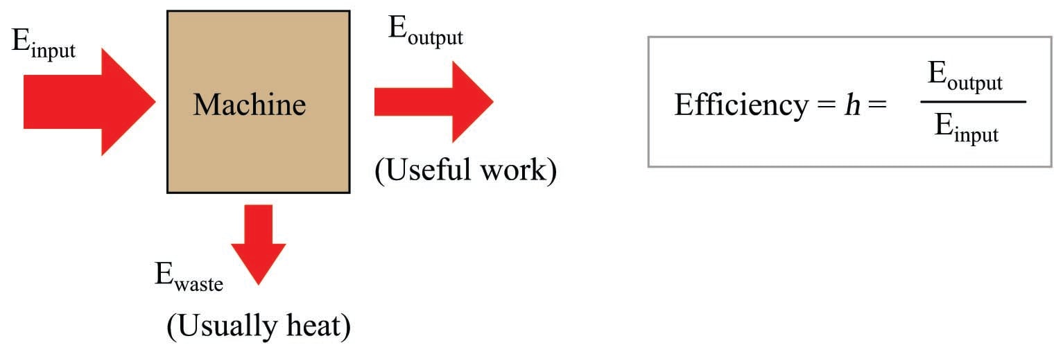
Ideally, these two will be equal, with all of the input energy translated losslessly into output energy. However, no machine is perfectly efficient although some simple machines come very close to achieving 100% efficiency. It is physically impossible to achieve an energy efficiency greater than 100%, as that would violate the Law of Energy Conservation.
Levers
Perhaps the most basic type of machine is the lever: a rigid beam pivoting on an axis. This axis may be something as simple as a round cylinder, a pointed wedge, or even a sophisticated bearing. In any case, the general term for the pivot point on a lever is fulcrum:

If we look at the lever’s motion at each end, we see that the distance the “output” end moves is a function of how far the “input” end moves as well as the ratio of lengths from each end to the fulcrum. Showing examples using three different classes of lever, each one with an \(8 \over 3\) length ratio:

The ratio of output force to input force (\(F_{out} \over F_{in}\)) is called the mechanical advantage of the machine. This ratio is always the reciprocal of the output versus input motion: if the output of the lever moves less than the input moves, the output force must be greater than the input force, and vice-versa. This makes perfect sense if you view a lever as a perfectly efficient machine where the output energy (work) must equal the input energy (work): since output energy is output force multiplied by output motion, and input energy is input force multiplied by input motion, in order for force to be multiplied, motion must be diminished.
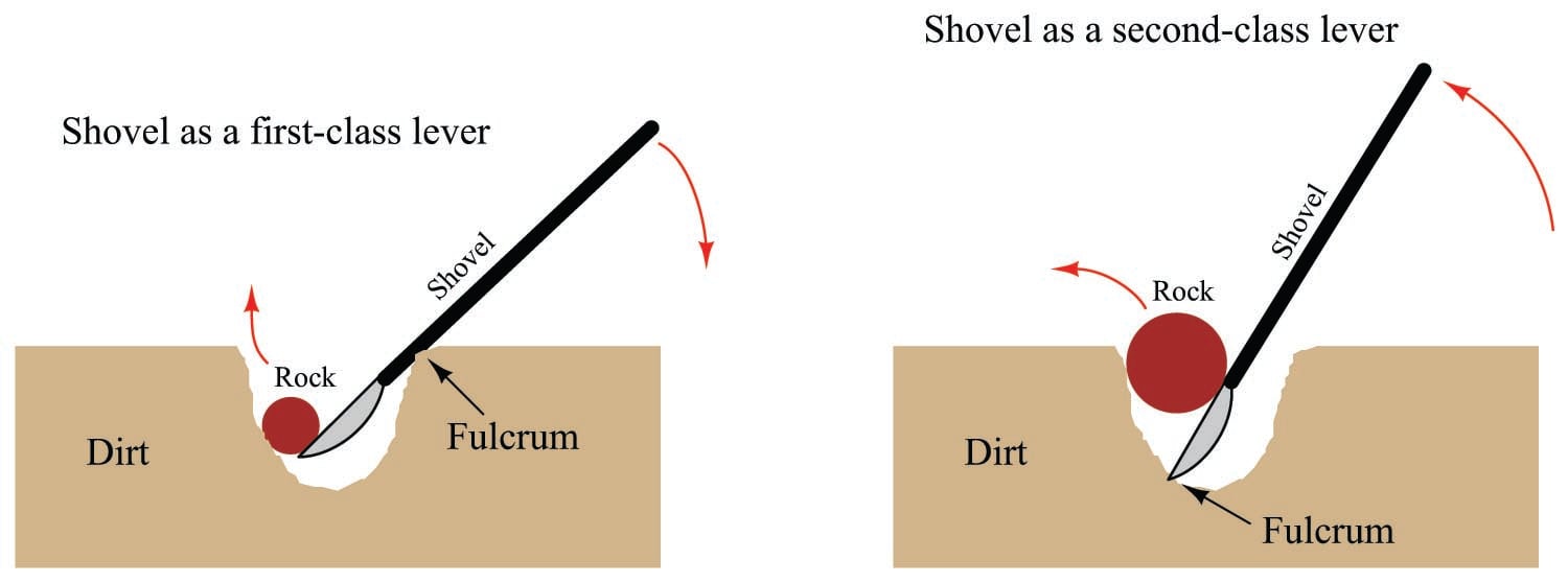
Levers abound in everyday life. A shovel, for example, functions as either a first-class lever or a second-class lever, depending on its use. In either case, it is being used as a force multiplier, the trade-off being that the person must move the handle a farther distance than the rock moves, thus exchanging motion for force:
Pulleys
Another simple and useful machine is a pulley and rope. A “pulley” is nothing more than a wheel with a groove cut around its circumference to guide a rope or cable, a bearing and axle supporting the wheel and allowing it to freely turn. A single pulley hung from an overhead support has the ability to convert downward motion of a rope into upward motion to hoist a load:
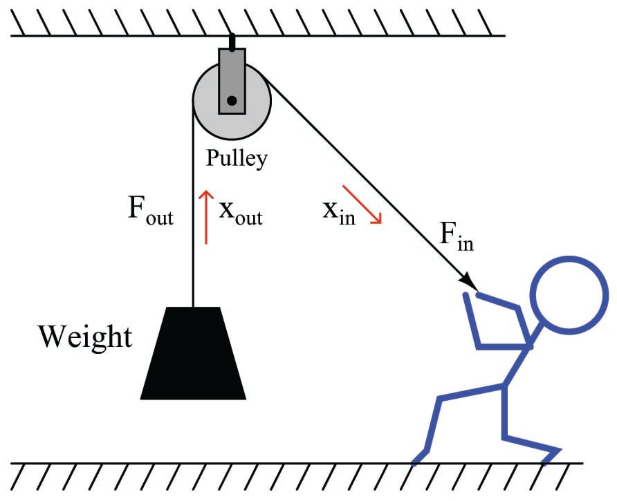
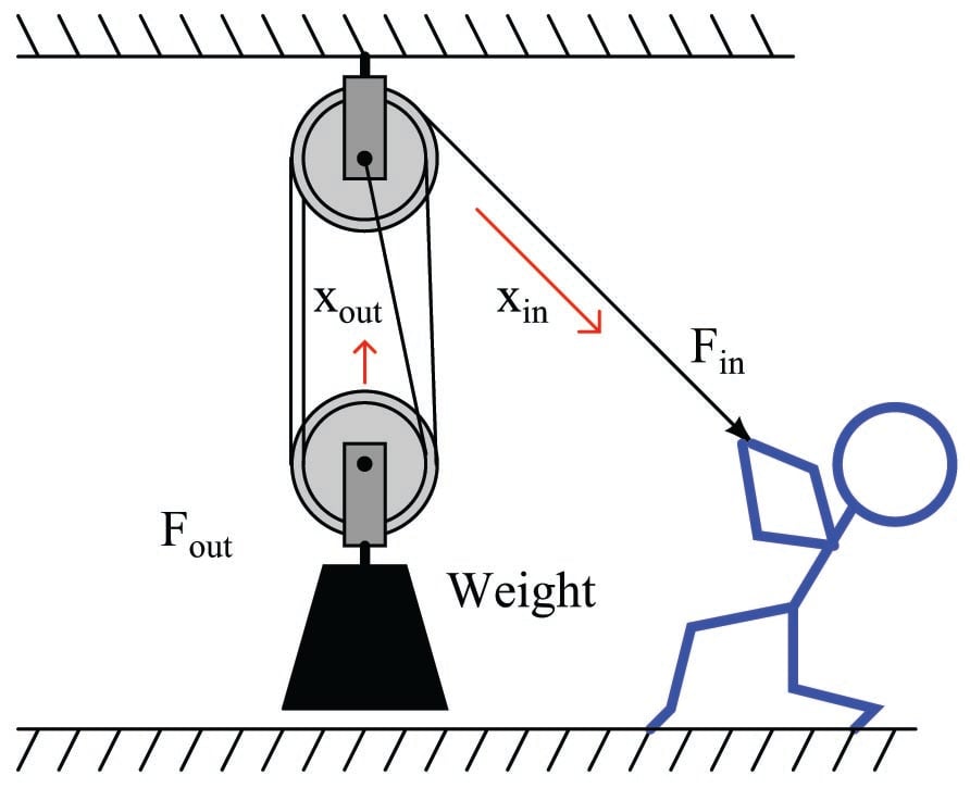
A single-pulley system such as this exhibits no mechanical advantage, because \(F_{out} = F_{in}\). If we get creative with multiple pulleys, however, we can achieve a mechanical advantage sufficient to hoist very heavy loads with modest input force:

Here, the weight is being supported by the tension within two ropes, not just one rope. Since the person’s force on the rope is what generates the rope’s tension, \(F_{in}\) is equal to rope tension, while \(F_{out}\) is equal to twice the rope’s tension. Thus, this simple machine has a mechanical advantage equal to 2. It also means the person’s motion while pulling the rope will be exactly twice the motion of the hoisted weight. Remember that we cannot cheat the Law of Energy Conservation: work in cannot be less than work out. If the output force is twice as much as the input force due to mechanical advantage, the output motion can only be half as much as the input motion.
The mechanical advantage of a pulley system may be extended beyond two by adding even more pulleys. This pulley system has a mechanical advantage of 4, since the weight is being supported by the tension of four ropes, while the person pulling only feels the tension of a single rope:
Here is where one must be careful in analyzing pulley systems with regard to mechanical advantage. The mechanical advantage in each of these examples was based on the number of ropes supporting the weight. So far, this also happened to equal the number of pulleys in the system. Lest anyone be tempted to determine mechanical advantage by simply counting pulleys, here is an example that breaks the pattern:
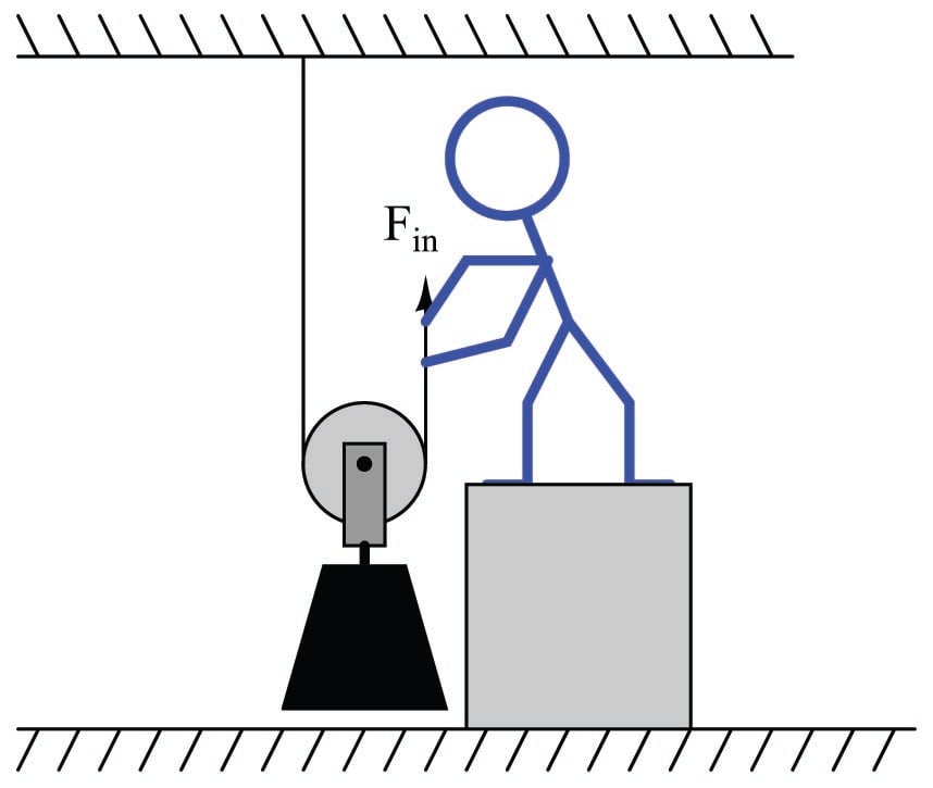
Here there is only one pulley in the system, yet the weight is being supported by the tension in two ropes and the person pulling on the rope only feels the tension of one rope, which means the system has a mechanical advantage of 2.
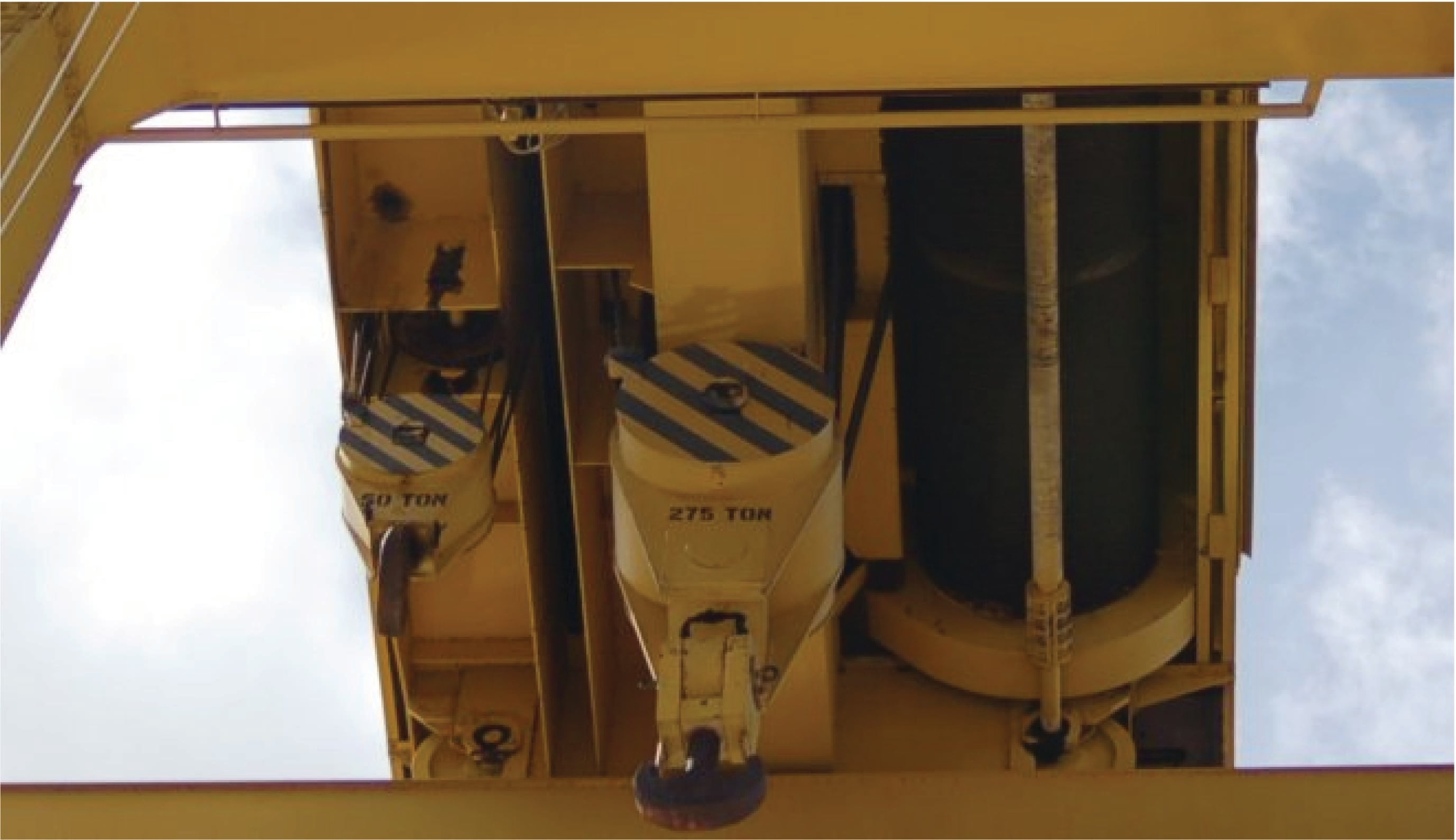
This simple technology is commonly used on cranes to provide huge amounts of lifting force with modest amounts of cable tension. In this photograph you can see the multiple pulleys and lifting cable of a large industrial crane:
Inclined planes
A wedge, also referred to as an inclined plane, is another type of simple machine. A large enough wedge such as a ramp is useful for producing a mechanical advantage to lift a weight equipped with wheels. Instead of hoisting the weight vertically, the weight is rolled up the diagonal incline of the ramp:

In moving the heavy weight a short distance vertically, the person pushes with much less force over a longer distance. The mechanical advantage of this ramp, therefore, is equal to the ratio of the ramp’s diagonal length (hypotenuse side) to its vertical height (opposite side). From the perspective of angle \(\theta\) shown in the illustration, this equates to the cosecant function (\(\csc \theta = {\hbox{hypotenuse} \over \hbox{opposite}}\)).
Another example of an inclined plane is a screw conveyor or auger, shown in the following photograph. The “fins” on the screw function as a long incline, wrapped around a central shaft:

Placed inside of a pipe and turned slowly, this simple machine moves semi-solid material linearly through the pipe.
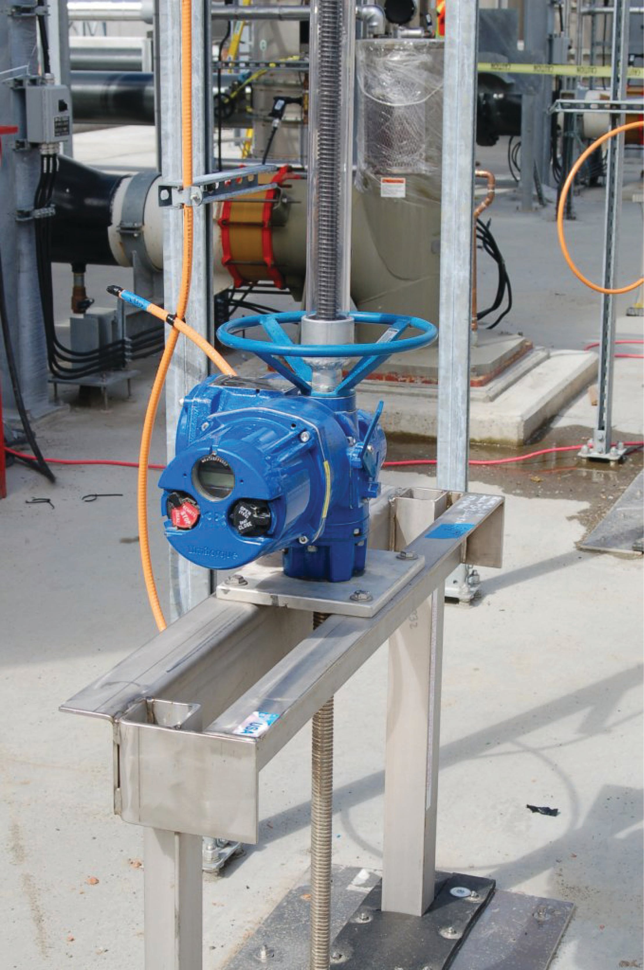
In a similar fashion, this electric valve actuator uses the principle of an inclined plane to raise and lower a heavy gate to control the flow of wastewater through channels at a municipal wastewater treatment facility. The long threaded shaft pulls upward on the heavy gate (not shown), moved by the turning action of a nut engaged with the shaft’s threads. The electric motor inside the blue-colored actuator turns the nut on command, raising or lowering the gate as needed:
Gears
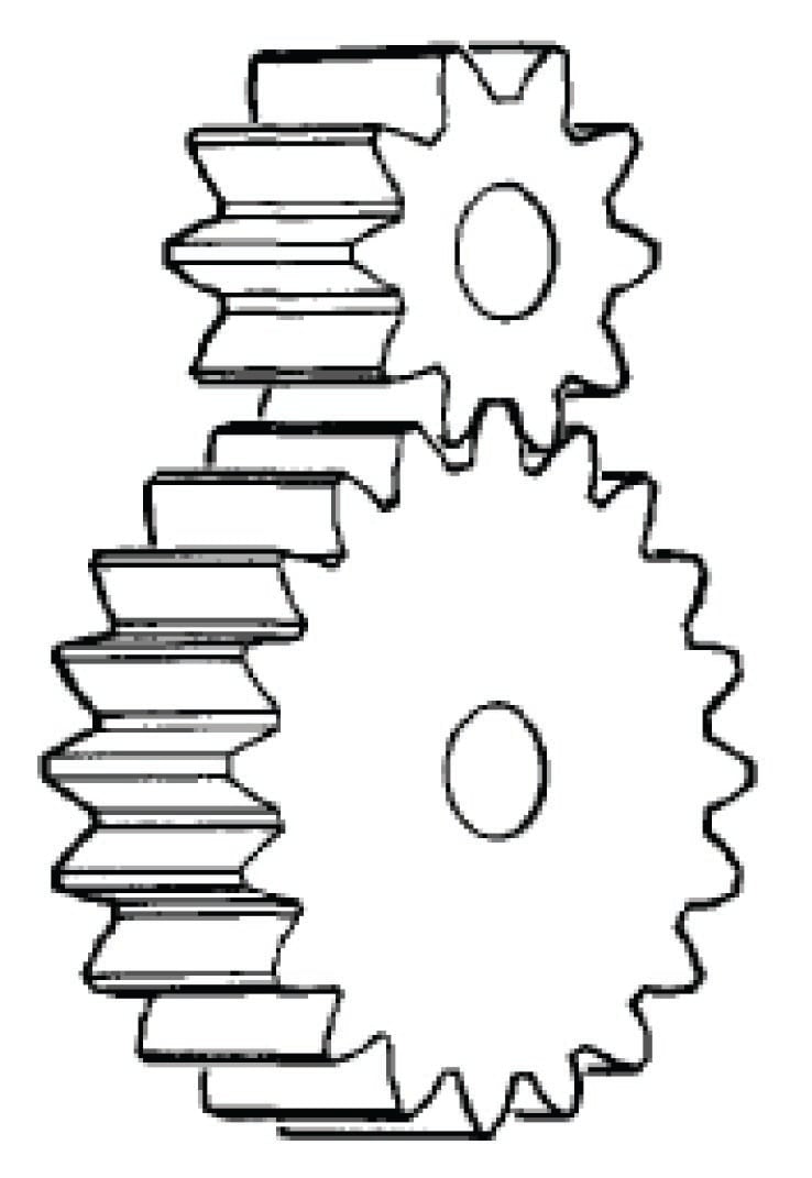
A gear set is another type of simple machine, part of a whole class of simple machines converting one form of rotary motion into another forms of rotary motion. A set of spur gears are shown here:

Each gear rotates about a central axis (usually a rotating shaft), the teeth of each gear cut into shapes designed to smoothly “mesh” together as the gears rotate. Gears may be thought of as levers, with the radius of each gear equivalent to the distance between the fulcrum and the force point on a level. The gear with the largest radius turns the slowest, and with the most torque.
The mechanical advantage of a gear set is simply the ratio of gear diameters. Another way to determine gear ratios is to count the number of teeth on each gear: since the teeth are all cut to the same size so as to smoothly mesh, the ratio of gear teeth will be proportional to the ratio of gear circumferences, which in turn must be proportional to the ratio of gear radii. If a gear set may be turned by hand, a simple counting of turns from input to output will also allow you to calculate the gear ratio. For example, if you turn one gear 15 revolutions to get the second gear to turn 4 revolutions, the mechanical advantage is \(15 \over 4\), or 3.75. As with levers, the gear that turns the farthest does so with less force (torque), and vice-versa. All simple machines work by trading motion for force, so that an increase in one necessarily results in a decrease of the other.
A variety of spur gear designs appears on this page. In this illustration, we see an external spur gear set with straight-cut teeth, perhaps the simplest style of gear:
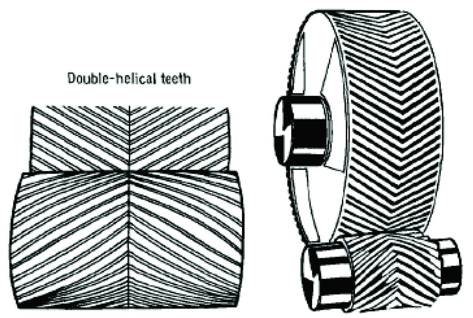
Next, we see variations on this design where the gear teeth are cut at angles instead of being parallel with the gears’ shafts. This causes the meshing of the gear teeth to be smoother and quieter, but also causes a thrust force to develop along the axis of the gear shaft, since the teeth act as inclined planes. A “double” helical gear pattern (also known as a herringbone gear due to its resemblance to a fish skeleton) cancels any thrust force by angling the teeth in opposite angles. Herringbone gear sets are quiet and strong, but tend to be more expensive to manufacture than single-helical gears:

The exposed gear sets commonly found in antique machinery provide excellent visual examples of gear designs. This next photograph shows sets of external spur gears. The upper photograph shows a pair of meshing spur gears with parallel teeth, while the lower photograph shows a set of four meshing spur gears with single-helical teeth, both sets of gears found on antique gasoline engines:


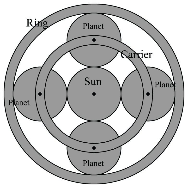
Another style of gear set is called planetary, because its shape resembles circular orbits of planets around a star. Planetary gear sets are exceptionally strong, and are capable of delivering multiple gear ratios depending on which gear (the “sun” gear, the “ring” gear, or the “planet” gears) is being held stationary, which gear is the input, and which gear is the output. If any two sets of gears are locked together such that they rotate at the same speed, the third gear in a planetary mechanism must also rotate at that same speed, for a 1:1 ratio. Typically, the planet gears are all anchored in their respective positions by a rotating frame called a carrier:

The particular planetary gear set shown in the above illustration uses two sets of helical gears (much like a herringbone design, only with two single-helical gears placed back-to-back instead of one gear with double-helical teeth) in order to eliminate thrust forces on the shafts.
Planetary gear sets are the standard type of gears used in automatic transmissions for automobiles. Different gear ratios (e.g. “Low”, “Drive”, “Overdrive”) are achieved in an automatic transmission by selecting which gears in a planetary gear set are input, output, and stationary. A series of clutches engage and disengage shafts to control which gears are input versus output, while a series of bands act as brakes to hold different gears stationary in the planetary gear set. These clutches and bands are all operated by hydraulic oil pressure inside the transmission, controlled either by a series of hydraulic relays and/or by an electronic computer telling the transmission when to shift.
The Synergy\(^{TM}\) gear drive system designed by Toyota for use in its line of hybrid gasoline-electric cars is a unique application of planetary gears. In the first-generation Toyota Prius, an electric motor/generator (“MG1”) is coupled to the sun gear, the internal-combustion (gasoline) engine is coupled to the planet carrier, and the driveshaft is coupled to the ring gear (as well as a second electric motor/generator “MG2”). This planetary gear set allows power to be transferred smoothly and with great flexibility between the engine, the motor/generator, and the driveshaft. Motor/generator MG1 functions as a kind of variable brake (in “generator” mode, passing its power to either the battery or to MG2) to slow down the sun gear to achieve an infinite number of effective gear ratios for the engine, and the gasoline engine may also be locked to keep the planet gear carrier from turning during all-electric operation.
With a simple set of parallel-shaft spur gears, the ratio of the gear set is simply the ratio of gear teeth (or of effective diameters). For example, if a spur gear set has 15 teeth on the driving gear (\(N_{driving}\) = 15) and 45 teeth on the driven gear (\(N_{driven}\) = 45), the gear ratio will be a 45:15 or 3:1 reduction in speed (multiplication in torque). Planetary gear sets are more complicated than this, as shown by the following table:
| Condition | Slow | Fast | Ratio (\(x:1\)) |
|---|---|---|---|
| Ring gear held stationary | Planet carrier | Sun | \({N_r \over N_s} + 1\) |
| Sun gear held stationary | Planet carrier | Ring | \({N_s \over N_r} + 1\) |
| Planet carrier held stationary | Ring | Sun | \(-{N_r \over N_s}\) |
| Any two locked together | — | — | 1 |
It is interesting to note that the only gear teeth (diameters) values factoring into these ratio calculations belong to the ring and sun gears. The negative sign for the stationary-carrier condition refers to the reversed rotation of the ring gear compared to the sun gear.
As always, one should strive to understand rather than memorize when learning anything new, and planetary gear set ratios are no exception to this rule. An excellent exercise is to mentally visualize each of the conditions listed in the table above, applied to a graphic image of a planetary gear set. Run a series of “thought experiments” on the gear set, where you imagine one of the three pieces being held stationary while one of the free pieces is turned. Ask yourself whether the third piece turns faster or slower than the other free piece. Then, imagine the sun gear growing or shrinking in size, and ask yourself how this change in sun gear size affects the speed ratio:
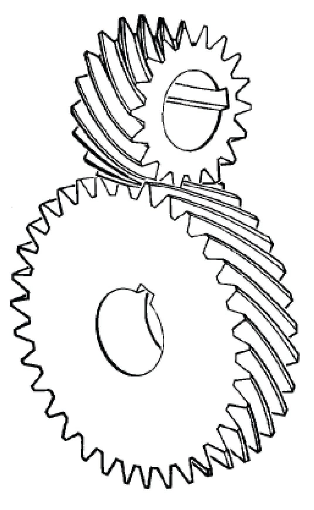
A variety of gear set designs with perpendicular shafts exist to transfer mechanical power around corners. First, we see a crossed helical spur gear. Like parallel-shaft helical spur gears, crossed helical gears generate thrust forces due to the action of the gear teeth as inclined planes:
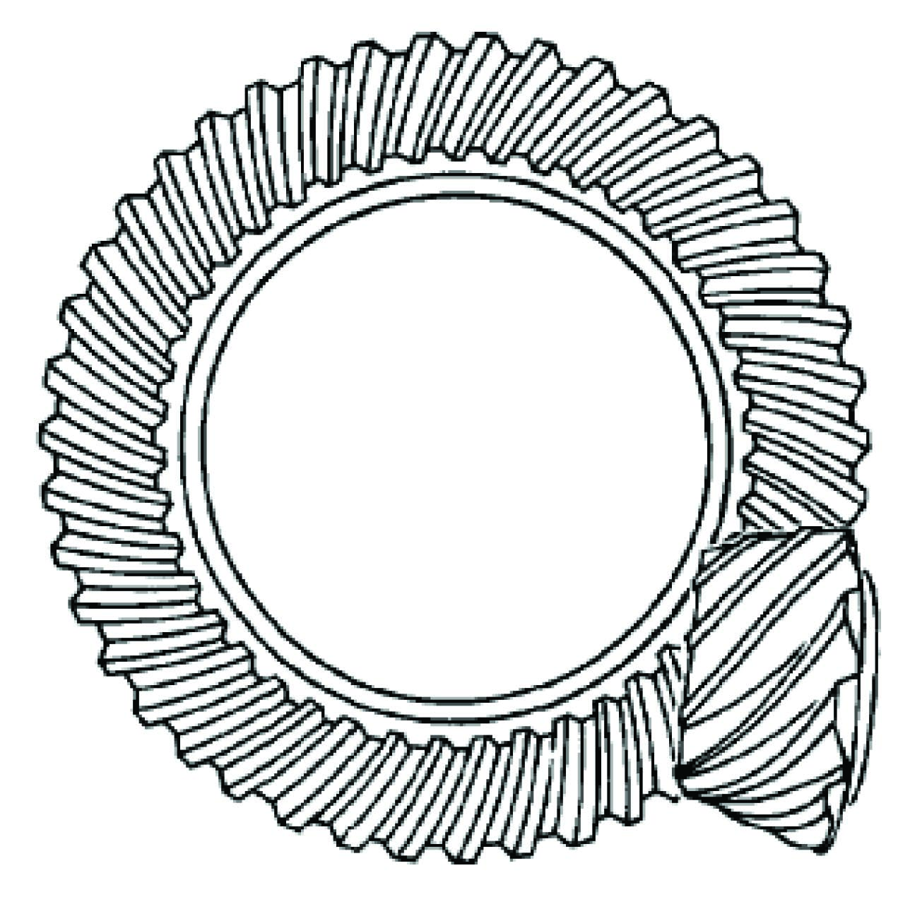
Next we see a bevel gear or miter gear set, where a pinion gear intersects with a ring gear to transfer mechanical power through perpendicular shafts. The left-hand illustration shows a straight-toothed bevel gear set, while the right-hand illustration shows a spiral-toothed bevel gear set.
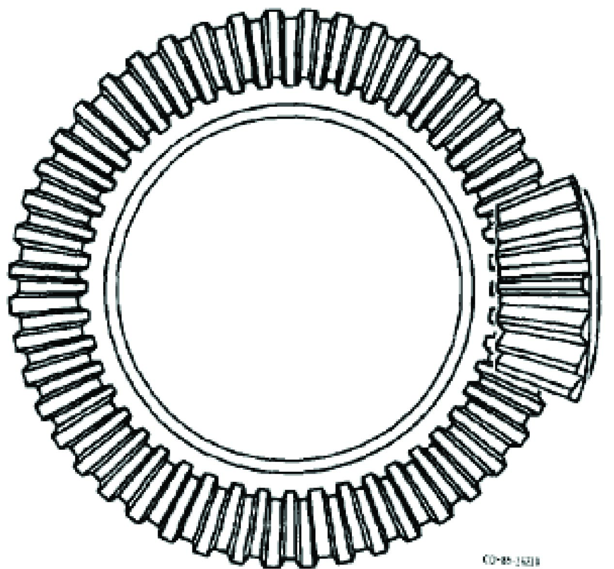

These two styles of bevel gears are analogous to the straight- versus helical- toothed variants of the spur gear, with similar characteristics: spiral-toothed bevel gears provide smoother and quieter operation than straight-toothed bevel gears, but at the expense of generating large thrust forces on the pinion gear shaft, and radial forces on the ring gear shaft.
An interesting variation on the bevel gear concept is the hypoid gear system, where the two shaft axes do not intersect. In this gear set, the gear teeth actually rub against each other rather than merely touch, necessitating special lubricant to tolerate the dynamic pressures and stresses. Hypoid gear sets are exceptionally strong and quiet-running, and became popular for automotive axle drive systems because they allowed the driveshaft (attached to the pinion gear) to be lower than the axles (attached to the ring gear), providing more floor space in the vehicle. The non-intersecting shaft centerlines also make it possible to place support bearings on both ends of the pinion gear for extra strength, as seen in heavy-duty truck axle designs:
A photograph of a hypoid gear set inside the differential of an automobile is shown here, the differential housing cover removed for inspection:

An important type of gear set used for perpendicular-shaft applications with large speed-reduction ratios is the worm gear. A worm gear resembles a screw whose threads engage with matching helical-cut threads on another gear called a worm wheel:

An interesting and useful feature of a worm gear set is that power transfer occurs easily from the worm screw to the worm wheel, but not so easily from the worm wheel to the worm screw due to friction between the teeth of the two gears. This means when the worm screw is not being turned by an outside force, even small amounts of friction between the screw threads and wheel teeth will effectively “lock” the worm wheel in place such that it cannot turn when an outside force acts on it. A practical example of a worm gear exploiting this feature is a hand-crank winch, where we desire the winch drum to remain locked in position when we let go of the hand-crank.
Another interesting feature of worm gears is that the gear ratio is simply the number of teeth on the worm wheel, since the tooth pitch on the circumference of the worm wheel defines what the thread pitch must be on the worm screw. For example, a worm wheel having 40 teeth around its circumference will exhibit a 40:1 speed-reduction ratio regardless of worm screw size, since there is only one worm screw thread pitch that will engage with the teeth on this worm wheel.
A real worm gear assembly may be seen in this next photograph, as one component of an antique farm implement. Here, a hand-wheel turns the work screw, which then turns the worm wheel and either lifts or drops the height of the implement’s blade:

The “one-way” action of a worm gear is advantageous in this application, so that the hand wheel does not spin on its own every time the implement’s blade encounters uneven ground. Wherever the hand wheel is set to adjust blade height, that blade height remains fixed until the hand wheel is turned to some new position.
It should be noted that modern worm gear sets, like nearly all types of gears, are more commonly found encased in a housings where they operate in a lubricated environment, sealed from contamination by dust and other matter both solid and liquid. Exposed gears are more commonly seen on antique machinery, where the mechanical stresses were low enough (i.e. low torque forces, large gears) to permit reliable operation of gears with the only lubrication typically being a coat of heavy grease smeared over the gear teeth.
As with other types of simple machines, gear sets may be combined into larger assemblies, with the over-all mechanical advantage (i.e. gear ratio) being the product of all individual gear ratios in the system. An example of a compound gear train is this helicopter transmission, designed to reduce the high-speed shaft rotation of the helicopter’s turbine engine down to a speed more suitable for the main rotor:
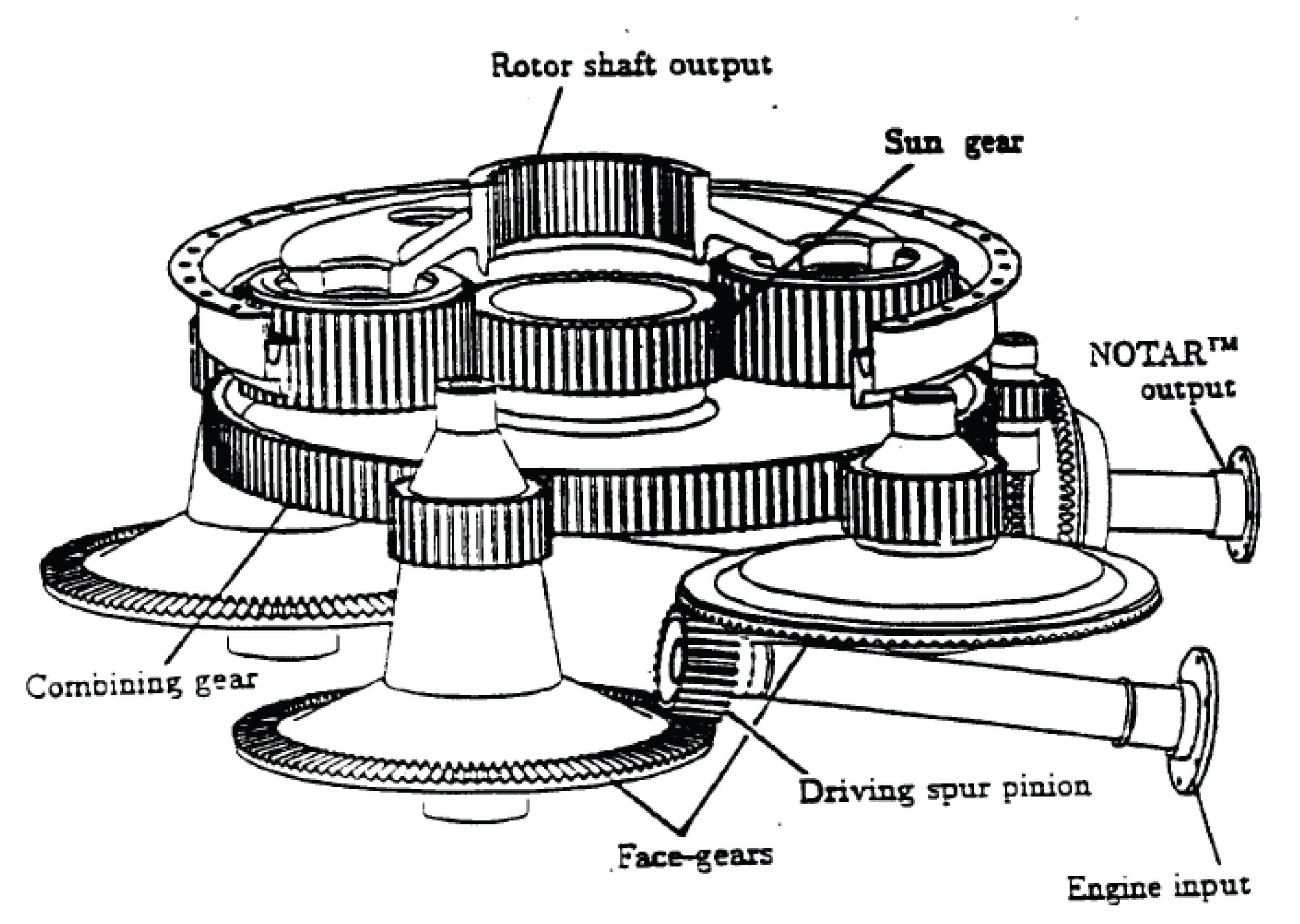
Mechanical shaft power flows from the turbine shaft (usually several thousand RPM) to the rotor (a few hundred RPM) in this transmission via several types of gears. First, the turbine shaft’s speed is reduced through multiple sets of bevel gears operating in parallel (from the “driving spur pinion” gear to the “face gears”). These multiple face gears then couple to a “combining” gear through a spur gear reduction. This combining gear then feeds power to a central “sun” gear in a planetary gear train. The “ring” gear of this planetary set is fixed to the case of the transmission so that it does not turn. Finally, four “planet” gears running in a common carrier assembly drive the helicopter’s rotor.
The following photograph shows a modern “gearbox” used to decrease the rotational speed of an electric motor, to turn an auger feeding grain out of a storage bin at a beer brewery. Like all modern gear sets, the gears inside this gearbox operate in a continuously-lubricated environment, sealed to prevent contaminants such as dust and water from entering:

A very large gearbox is shown in this next photograph, used in the head of a Vestas wind turbine to “step up” the slow rotational speed of the turbine to the much higher rotational speed of the electric generator. Planetary gears are used in wind turbine gearboxes due to their ruggedness and relatively compact size:
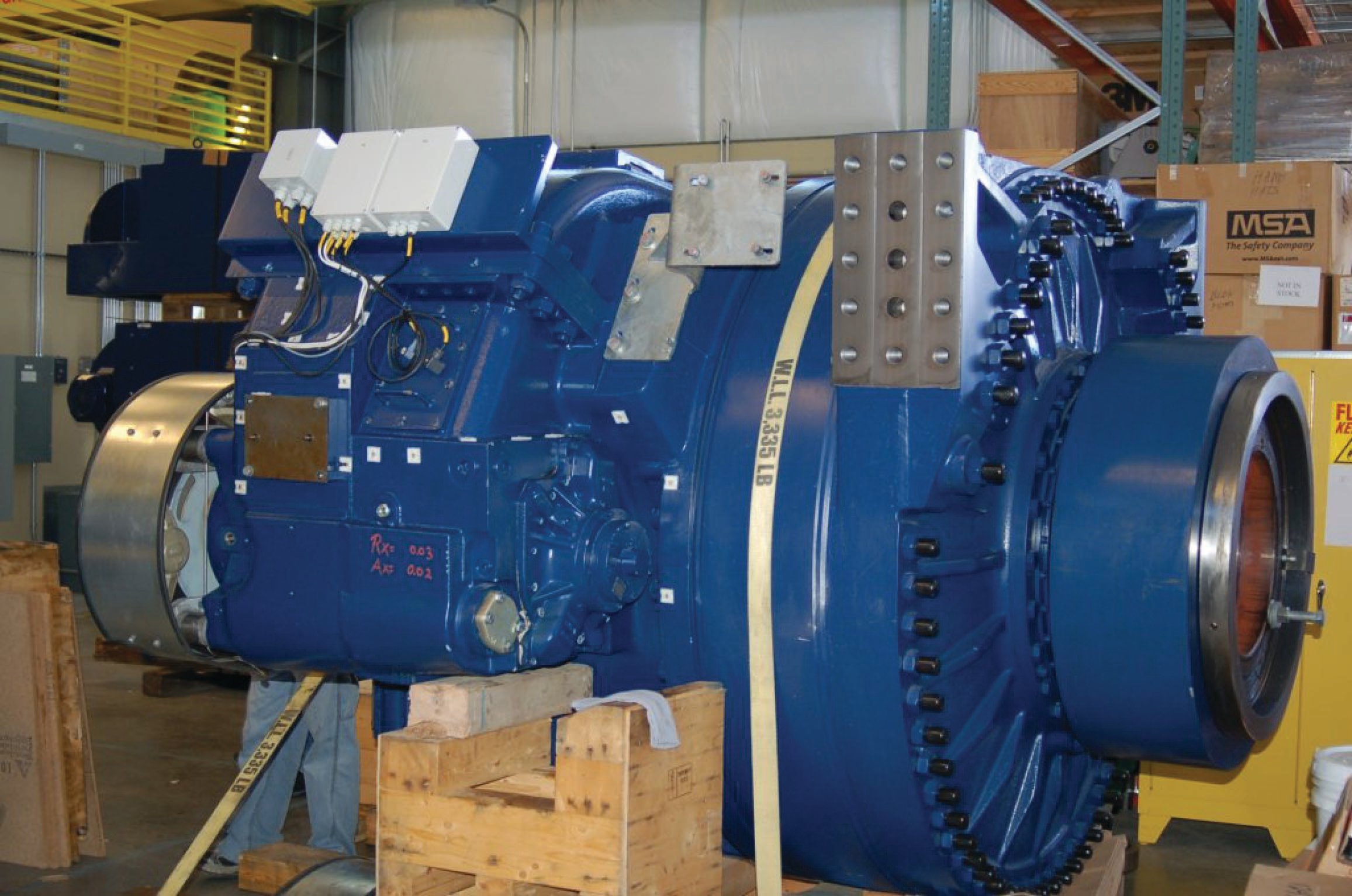
The ratio of this wind turbine’s gear set happens to be 111.5:1, with the generator turning 111.5 times faster than the turbine blades (but with only \(1 \over 111.5\) the torque of the turbine blades, of course)!
Belt drives
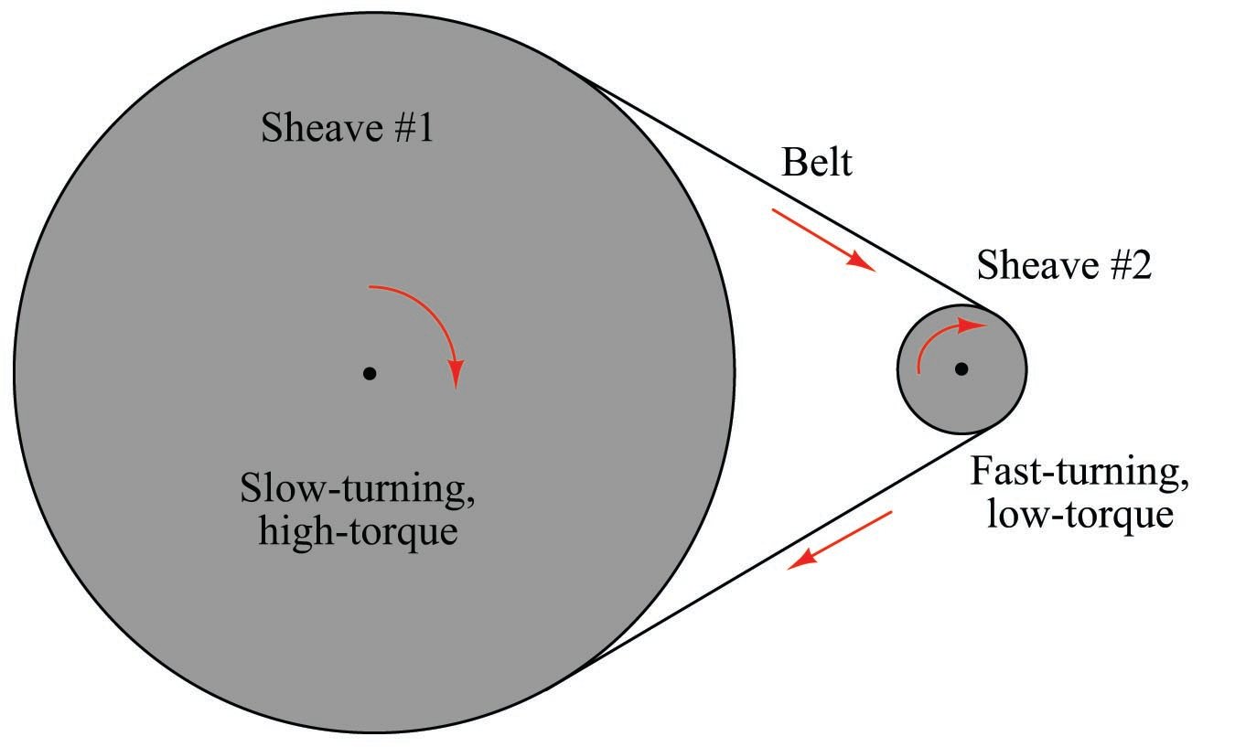
A sheave is very similar in form and function to a pulley, but designed to grip a flexible belt rather than a rope or a cable. Unlike a pulley which is designed to turn freely to re-direct the tension of a rope, a sheave works more like a gear to couple the belt’s motion to a rotating shaft. The mechanical advantage of a pair of sheaves coupled by a common belt is simply the ratio of sheave radii, just like gears:
The following photograph shows a triple-belt drive from an electric motor to an agitator on the bottom of a sawdust storage bin:

As indicated by the respective sheave diameters, the electric motor turns much faster than the agitator, while the agitator spins with much greater torque than the motor.
Most modern belt drives are either V-belt or toothed belt, referring to the shapes of the belt and how they engage with the sheave. The triple-belt drive system for the sawdust agitator shown in the previous photograph used V-belts. A V-belt has a V-shaped cross-section, and sits in a V-shaped groove around the circumference of the sheave. Toothed belts almost resemble chains, in that their inner surface is characterized by regularly-spaced perpendicular ribs designed to engage with matching cavities machined into the circumference of the sheave. The advantage of a toothed belt is that it cannot slip on the sheave if overloaded, unlike a V-belt. A toothed belt is firmly “locked” into place on the sheave’s circumference so long as proper belt tension is maintained.
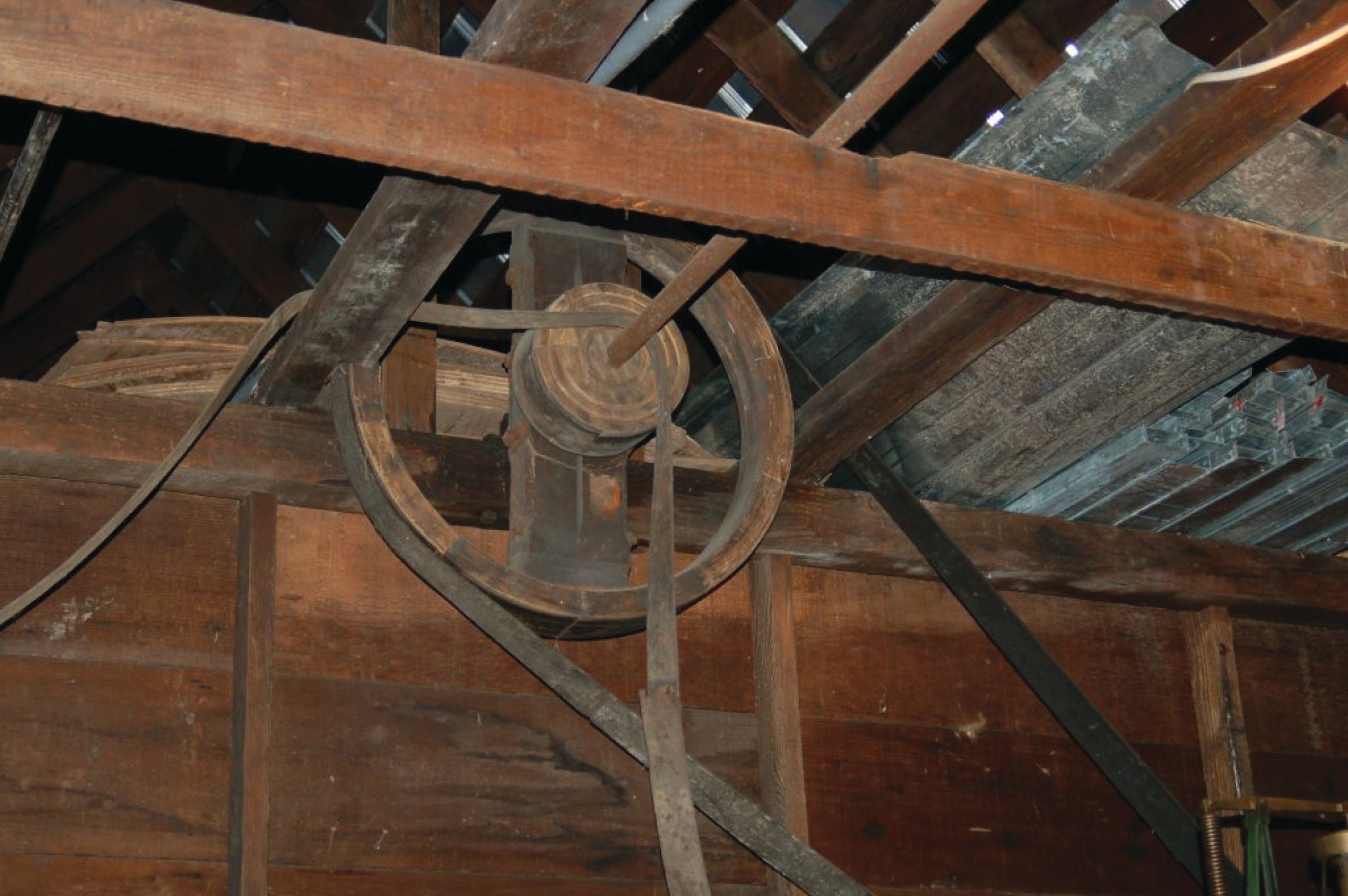
An older belt-and-sheave technology is the flat belt. Here, the sheave’s circumference is flat, and the belt itself is nothing more than a strip of flexible material with no special shape. The following photograph shows an antique flat belt drive in a workshop, where a central shaft ran along the ridge of the ceiling to power several machines in the shop, the shaft itself turned continuously by either a water turbine or a steam engine:
Flat belts are still used in modern times, but they tend to be much wider than V-belts or toothed belts of comparable rating in order to deliver adequate “grip” on the sheave. Also, sheave-to-sheave alignment is much more critical for a flat belt, which has no guides on the sheave to keep it centered.
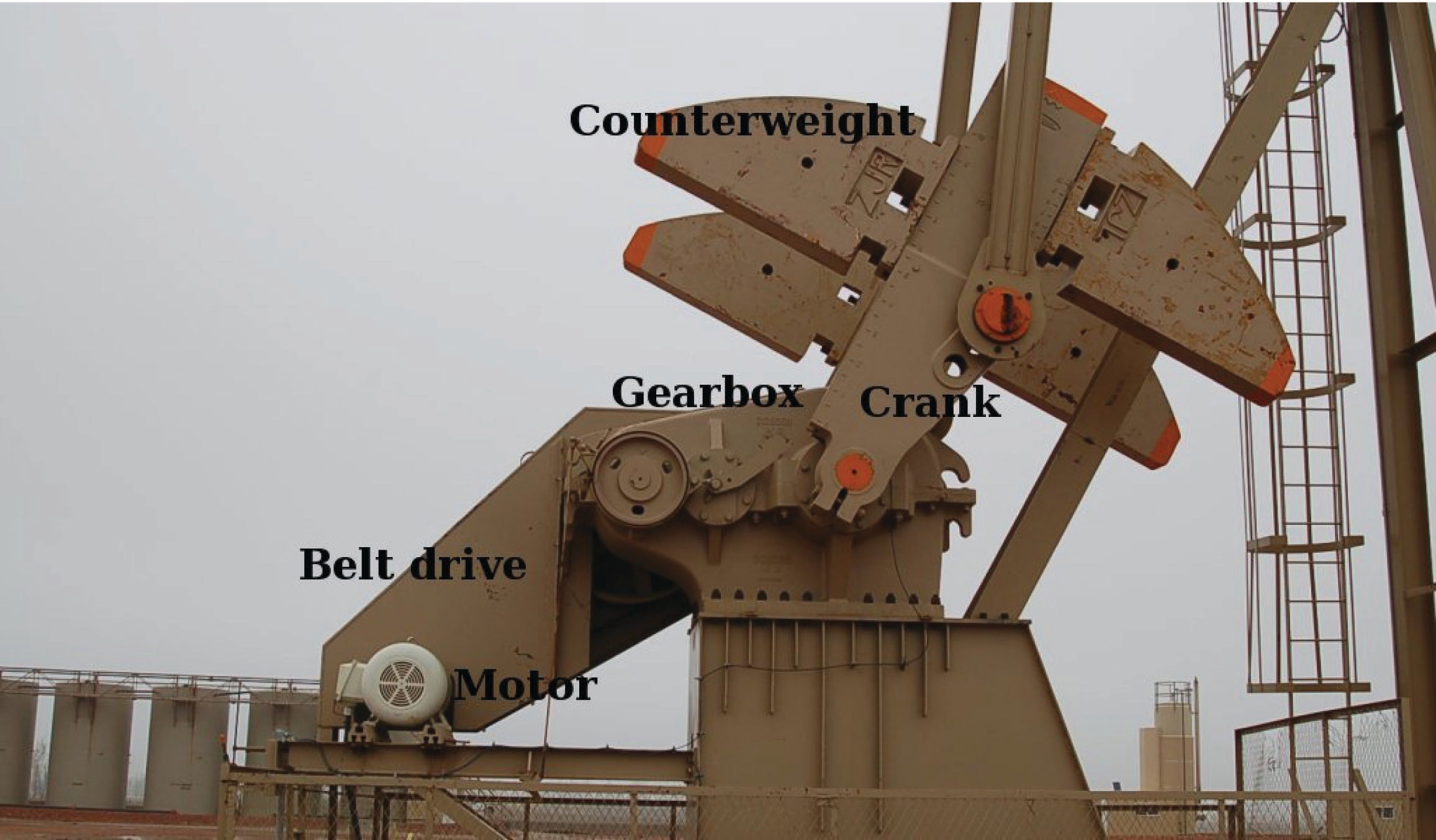
Like gear sets, industrial belt drive systems are typically shrouded for cleanliness and for personnel safety. Sheet-metal enclosures such as the one covering the top of this V-belt drive system on a “walking-beam” style of oil field pump. The sheet-metal enclosure protects the belts and sheaves from rain and snow. You will also note a large gearbox following the belt drive, further reducing rotational speed from the electric motor to the pump’s counter-weighted crank:
Belts of all styles are subject to wear and fatigue, and as such must be periodically replaced. Some belt drive systems employ tensioner mechanisms which maintain consistent belt tension by applying a constant force to the belt. Small tensioners are usually spring-loaded, while large belt tensioners (particularly conveyor belts) are loaded by the weight of a large mass. Minimum belt tension is extremely important for belt drives, as loose belts will begin to “slip” under load and quickly fail if the problem is not remedied.
When multiple belts are used to distribute loading between belts in high-power drive systems, it is important that all belts be replaced simultaneously, never partially. If a new belt is installed next to an old belt on the same sheave, the old belt will run “loose” and not bear its full share of the load, thus overloading the other (new) belt(s) in the drive system.
Chain drives
Sprockets are identical in function to sheaves, using link chain rather than belt to couple the two rotating pieces together. Bicycles are perhaps the best-known example of sprockets and chains from everyday life, being the most efficient simple machine for the purpose of coupling a person’s leg power to a rotating wheel for propulsion. Like gear sets, the mechanical advantage ratio of a sprocket set may be determined by counting teeth on each sprocket and then dividing one tooth count by the other, or empirically by rotating one sprocket by hand and counting the number of turns (revolutions) each sprocket makes.
The following photograph shows a pair of sprockets linked together with a roller chain. The sprocket ratio here is 1:1, as both sprockets share the same number of teeth:

Bicycles use sprockets and a chain to transfer power from the crank to the rear wheel. Here, a multi-speed sprocket assembly allows the rider to select the best ratio (i.e. mechanical advantage) for riding at different speeds and in different conditions. Three sprockets on the crank and eight sprockets on the wheel give a theoretical maximum of 24 different “speeds” or “gears” from which to select:
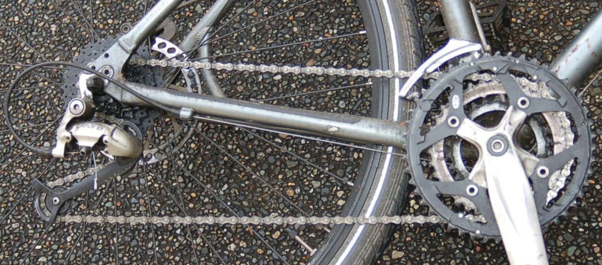
Chain drive systems require thorough lubrication and freedom from dirt and other abrasive particles in order to deliver full service life. Open-chain systems such as the two shown in the above photographs are challenging to maintain in good working order for these reasons.
