 Facebook
 Google
 GitHub
 Linkedin
Tube and Tube Fittings
Tube, like pipe, is a hollow structure designed to provide an enclosed pathway for fluids to flow. In the case of tubing, it is usually manufactured from rolled or extruded metal (although plastic is a common tube material for many industrial applications). This section discusses some of the more common methods for joining tubes together (and joining tube ends to equipment such as pressure instruments).
One of the fundamental differences between tube and pipe is that tube is never threaded at the end to form a connection. Instead, a device called a tube fitting must be used to couple a section of tube to another tube, or to a section of pipe, or to a piece of equipment (such as an instrument). Unlike pipes which are thick-walled by nature, tubes are thin-walled structures. The wall thickness of a typical tube is simply too thin to support threads.
Tubes are generally favored over pipe for small-diameter applications. The ability for skilled workers to readily cut and bend tube with simple hand tools, as well as the ability to repeatedly break and re-make tube connections without compromising the integrity of the seals, makes tube the preferred choice for connecting instruments to process piping. When used as the connecting units between an instrument and a process pipe or vessel, the tube is commonly referred to as an impulse tube or impulse line.
Compression Tube Fittings
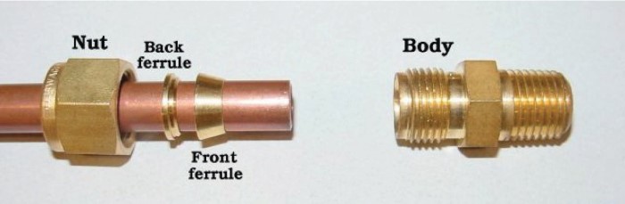
By far the most common type of tube fitting for instrument impulse lines is the compression-style fitting, which uses a compressible ferrule to perform the task of sealing fluid pressure. The essential components of a compression tube fitting are the body, the ferrule, and the nut. The ferrule and body parts have matching conical profiles designed to tightly fit together, forming a pressure-tight metal-to-metal seal. Some compression fitting designs use a two-piece ferrule assembly, such as this tube fitting shown here (prior to full assembly):
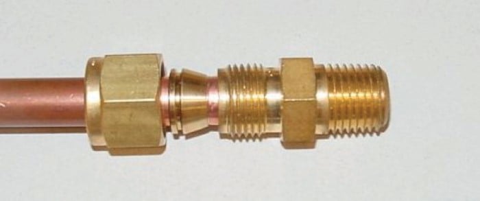
Just prior to assembly, we see how the nut will cover the ferrule components and push them into the conical entrance of the fitting body:
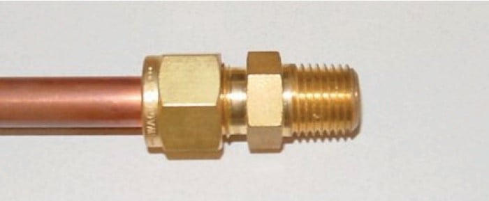
After properly tightening the nut, the ferrule(s) will compress onto the outside circumference of the tube, slightly crimping the tube in the process and thereby locking the ferrules in place:
When initially assembling compression-style tube fittings, you should always precisely follow the manufacturer’s instructions to ensure correct compression. For Swagelok-brand instrument tube fittings 1 inch in size and smaller, the general procedure to “swage” a new connector to a tube is to tighten the nut 1-1/4 turns past finger-tight. Insufficient turning of the nut will fail to properly compress the ferrule around the tube, and excessive turning will over-compress the ferrule, resulting in leakage. After this initial “swaging,” the connector may be separated by loosening the nut until it no longer engages with the body, then the connection may be re-made by threading the nut back on the body until finger-tight and then gently tightening with a wrench until snug (no additional 1-1/4 turns!!!).
Swagelok provides special gauges which may be used to measure proper ferrule compression during the assembly process. The design of the gauge is such that its thickness will fit between the nut and fitting shoulder if the nut is insufficiently tightened, but will not fit if it is sufficiently tightened. Thus the gauge has the ability to reveal an under-tightened fitting, but not an over-tightened fitting. These gauges fit easily in the palm of one’s hand:
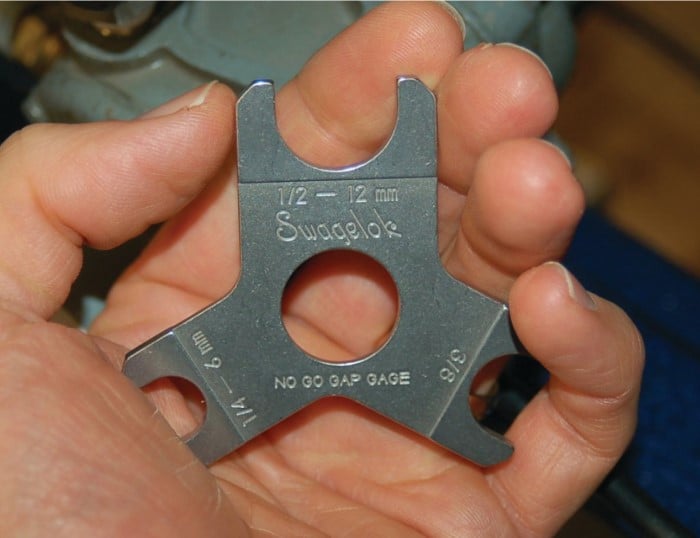
Such gauges are referred to in the industry as no-go gap gauges, because their inability to fit between the nut and body shoulder of a tube fitting indicates a properly-tightened fitting. In other words, the gauge fit will be “no-go” if the tube fitting has been properly assembled.
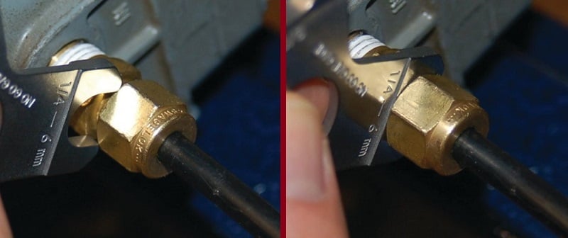
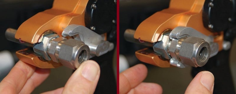
Photographs showing one of these gauges testing a properly-tightened fitting (left) versus an under-tightened fitting (right) appear here:
Parker is another major manufacturer of instrument tube fittings, and their product line uses a single-piece ferrule instead of the two-piece design preferred by Swagelok. Like Swagelok fittings, Parker instrument fitting sized 1/4 inch to 1 inch require 1-1/4 turns past hand tight to properly compress the ferrule around the circumference of the tube. Parker also sells gauges which may be used to precisely determine when the proper amount of ferrule compression is achieved.
What a gap gauge will not indicate is over-tightening. Over-tightening of a compression fitting is just as bad as under-tightening, as the fitting cannot form a robust seal once the ferrule and tube have been deformed. An example of an over-tightened Swagelok two-piece ferrule (left) on a plastic tube appears in the following photograph, next to a properly swaged ferrule (right):
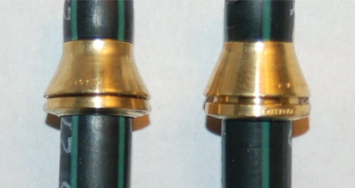
Note the lack of a substantial gap between the two ferrule pieces in the over-tightened example. Note also the steeper cone taper of the over-tightened front ferrule, as a result of being pushed too deep inside the fitting body.
Regardless of the brand, compression-style instrument tube fittings are incredibly strong and versatile. Unlike pipe fittings, tube fittings may be disconnected and reconnected with ease. No special procedures are required to “re-make” a disassembled instrument fitting connection: merely tighten the nut “snug” to maintain adequate force holding the ferrule to the fitting body, but not so tight that the ferrule compresses further around the tube than it did during initial assembly.
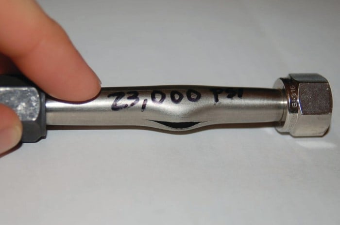
A very graphic illustration of the strength of a typical instrument tube fitting is shown in the following photograph, where a short section of 3/8 inch stainless steel instrument tube was exposed to high liquid pressure until it ruptured. Neither compression fitting on either side of the tube leaked during the test, despite the liquid pressure reaching a peak of 23000 PSI before rupturing the tube:
Common Tube Fitting Types and Names
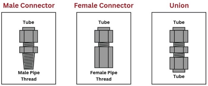
Tube fittings designed to connect a tube to pipe threads are called connectors. Tube fittings designed to connect one tube to another are called unions:
If a tube union joins together different tube sizes rather than tubes of the same size, it is called a reducing union.
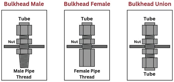
A variation on the theme of tube connectors and unions is the bulkhead fitting. Bulkhead fittings are designed to fit through holes drilled in panels or enclosures to provide a way for a fluid line to pass through the wall of the panel or enclosure. In essence, the only difference between a bulkhead fitting and a normal fitting is the additional length of the fitting “barrel” and a special nut used to lock the fitting into place in the hole. The following illustration shows three types of bulkhead fittings:
Tubing elbows are tube connectors with a bend. These are useful for making turns in tube runs without having to bend the tubing itself. Like standard connectors, they may terminate in male pipe thread, female pipe threads, or in another tube end:
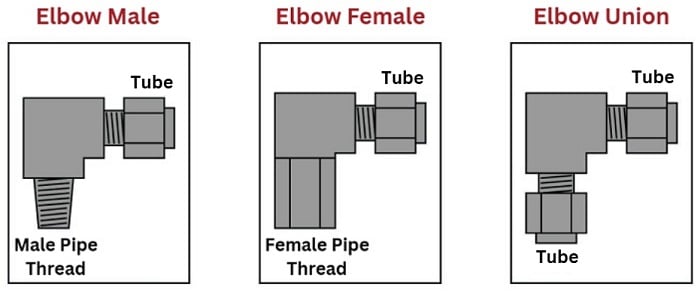
These elbows shown in the above illustration are all 90\(^{o}\), but this is not the only angle available. 45\(^{o}\) elbows are also common.
Tee fittings join three fluid lines together. Tees may have one pipe end and two tube ends (branch tees and run tees), or three tube ends (union tees). The only difference between a branch tee and a run tee is the orientation of the pipe end with regard to the two tube ends:
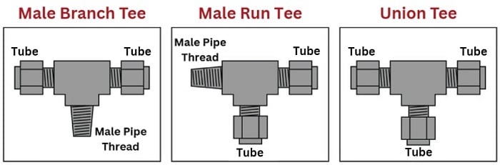
Of course, branch and run tee fittings also come in female pipe thread versions as well.
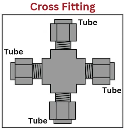
A variation of the theme of union tees is the cross, joining four tubes together:
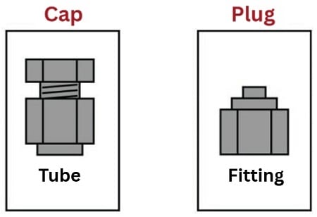
Special tube fittings are made to terminate tube connections, so they are sealed up instead of open. A piece designed to seal off the end of an open tube is called a cap, while a piece designed to seal off the open end of a fitting is called a plug:
Bending Instrument Tubing
Tube bending is something of an art, especially when done with stainless steel tubing. It is truly magnificent to see a professionally-crafted array of stainless steel instrument tubes, all bends perfectly made, all terminations square, all tubes parallel when laid side by side and perfectly perpendicular when crossing.
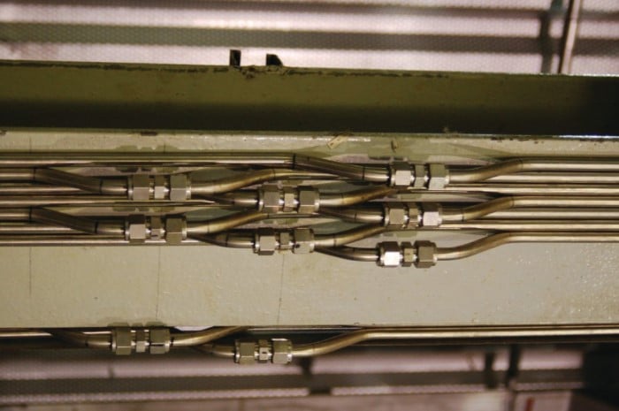
If possible, a goal in tube bending is to eliminate as many connections as possible. Connections invite leaks, and leaks are problematic. Long runs of instrument tubing made from standard 20 foot tube sections, however, require junctions be made somewhere, usually in the form of tube unions. When multiple tube unions must be placed in parallel tube runs, it is advisable to offset the unions so it is easier to get a wrench around the tube nuts to turn them. The philosophy here, as always, is to build the tubing system with future work in mind. A photograph of several tube junctions shows one way to do this:
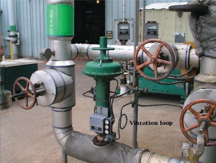
If an instrument tube must connect between a stationary object and a vibrating object, a straight (square) run of tube is actually not desirable, since it will not have much flexibility to absorb the vibration. Instead, a vibration loop should be made in the tube, giving it the necessary elasticity to tolerate the vibrational stresses. An example of a vibration loop placed in the air supply tube going to a control valve appears in this photograph:
When bending such a loop, it is helpful to use the circumference of a large pipe as a mandrel to form the tube rather than attempt to form a loop purely by hand.
Special Tubing Tools
A variety of specialized tools exist to help tubing installers work with compression-style tube fittings. One of these special devices is an electronic power tool manufactured by American Power Tool expressly for use with instrument tube fittings:
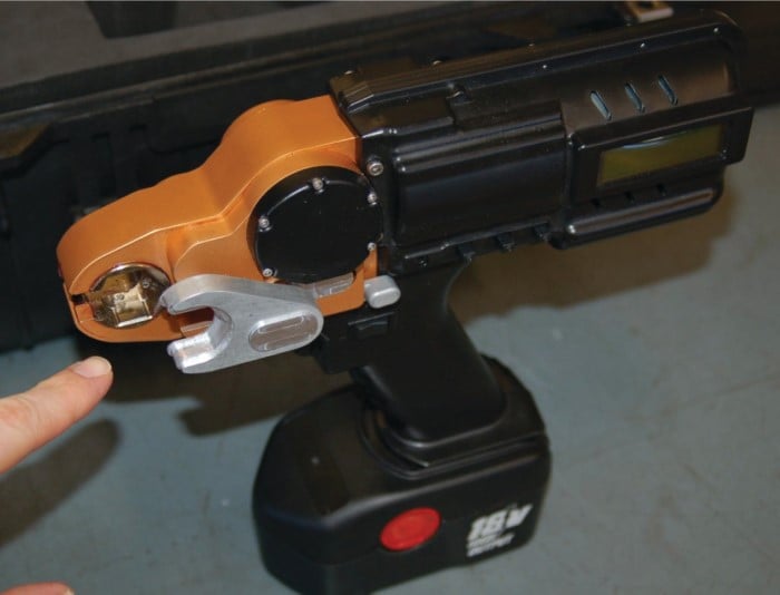
The Aeroswage SX-1 has a microprocessor-controlled electric motor programmed to rotate a tube fitting’s nut to a precise angular dimension, in order to properly swage the fitting. The tool comes complete with a holding jig to engage the body of the tube fitting, in order that all tightening torque is borne by the tool and not imposed on the person operating the tool:
Not only does this feature reduce the amount of stress placed on the tube fitter’s hand and wrist, but it also enables the tool to be used in the demanding environment of zero gravity, for example aboard a space station. In such an environment, torque applied to the tool operator could be disastrous, as the human operator has no weight to stabilize herself.
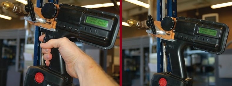
This next pair of photos shows how the tool is able to support itself on a piece of stiff (\(1 \over 2\) inch stainless steel) tubing, and indeed may even be operated hands-free:
The amount of rotation is programmable, enabling the tool to be used with different kinds of fittings. For standard industrial Swagelok compression fitting sizes (\(1 \over 4\) inch, \(3 \over 8\) inch, and \(1 \over 2\) inch), the recommended swaging rotation of 1-1/4 turns may be entered into the tool as a tightening angle of 450 degrees:

Being a microprocessor-controlled device, the SX-1 has the ability to digitally record all actions. This is useful in high-reliability production environments (e.g. aerospace tube installation) where individual tube fitting data are archived for safety and quality control purposes. This data may be downloaded to a personal computer through a serial port connection on the side of the tool. Here you can see the tool’s digital display showing the recorded action number, tightening angle, date, and time:

For large instrument compression fittings, hydraulic swaging tools are also available to provide the force necessary to properly compress the ferrule(s) onto the tube. Instrument tube manufacturers will provide specific recommendations for the installation of non-standard tube types, sizes, and materials, and also recommend particular swaging tools to use with their fittings.

This section is interesting because of the option of tubing for certain applications. Of course, if pressure is not too high you could use a simple push to connect option rather the presented nuts and ferrule option.