Tutorial: First Program With Phoenix Contact’s PLCnext Platform
Learn how to get started with Phoenix Contact’s PLCnext and Engineer software, a platform that ultimately provides a PLC environment for plant control as well as an OS for more advanced IIoT projects.
As we examine the scope of modern control systems around the world, there are three distinct categories of controllers.
At the most basic level, we find the traditional PLC (or PAC), which allows digital and analog I/O and communication with networked equipment. These machines execute some ladder logic, function block, or structured text code. The PLC is simple but highly effective, and it’s usually fairly simple to troubleshoot (relative to the following systems).
Residing at the more advanced level, the IPC is a computer with an operating system (most often a version of Linux or Windows) that’s packed inside a fanless or otherwise hardened case. Although it provides incredible flexibility for program design, it also tends to be quite complex and mystifying for control engineers.
In between these platforms, we find a rapidly emerging controller class given a variety of titles like an ‘IIoT Controller’. At the core, a PLC works alongside an IPC, allowing the familiar IEC 61131 programming interface for plant control, while a simultaneous operating system allows custom project development for projects far beyond the simple PLC scope.
In this project article, we’ll explore an example of this third controller category: the PLCnext IIoT Controller by Phoenix Contact.
We will establish a connection between the programming computer and the PLC, and download a simple ‘hello world’ ladder program, using a PNP sensor to activate a single digital output.
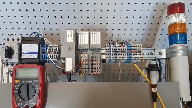
Figure 1. My first test bench setup for the PLCnext with one digital input and one digital output.
Prerequisites for PLCnext Programming
There are three basic necessities to creating a simple program for the PLCnext.
We must have the PLC itself (including one I/O module), the PLCnext Engineer software, and, in my experience, we also need to verify or obtain a specific .NET package on our programming PC.
Project Hardware (The PLC)
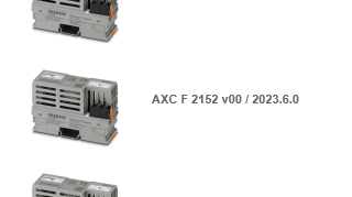
In this relatively simple example, we will need only the PLCnext controller and one I/O module. I have used the AXC F 2152 controller and the AXL F combination module with 8x inputs and 8x outputs.
Assembly note: when connecting these modules to a DIN rail, connect the bus bases for all modules and snap them onto the DIN rail first. Then, plug the controller and module(s) straight onto the bases in the appropriate order.
PLCnext Engineer (The Programming Software)
Download and install the programming software from the Phoenix Contact website. The target download is called PLCnext_Engineer_Setup and currently lists a 2024.0.3 version, although this may be updated in the future. The size is around 800 MB.
Microsoft .NET Version
As I started my own PLCnext journey, I encountered an error upon compiling a project: my laptop didn’t contain the proper version of Microsoft .NETCore. I found that version 7.0.16 was sufficient, and once I installed this package, the project compiled with no problems.
- Check the version on your own PC at: C:\Program Files (x86)\dotnet\shared\Microsoft.NETCore.App (Mine contained only 5.0.1)
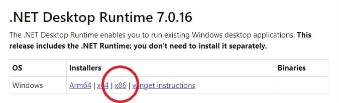
- If your PC does not contain a 7.0 version, navigate to the .NET download site.
- Locate the “.NET Desktop Runtime 7.0.16” and download then install the x86 version (note: PLCnext engineer only looks within the x86 folder, and newer versions may also work; I have not exhaustively tested all .net versions).
- Restart your computer to verify the installation.
Creating a Project in PLCnext Engineer
Well, we’ve devoted almost a full article just to setting up the programming environment. Now it’s time to create and download a project!
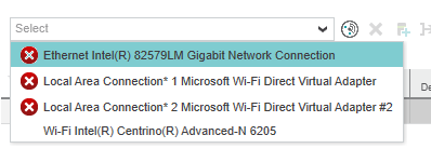
Before opening the PLCnext Engineer software, connect the PLC to the PC using an Ethernet cable plugged into the X1 slot on the controller. The software scans any active network cards on startup, so if you plug in the cable after starting, the software might not consider the Ethernet as ‘active’ as you can see from the red X icon in the Ethernet connection below. Simply restart the software if you encounter this.
Open PLCnext Engineer and start a new project, choosing the proper controller. There are some templates available for various controllers, and using the AXC F 2152 can speed the process.
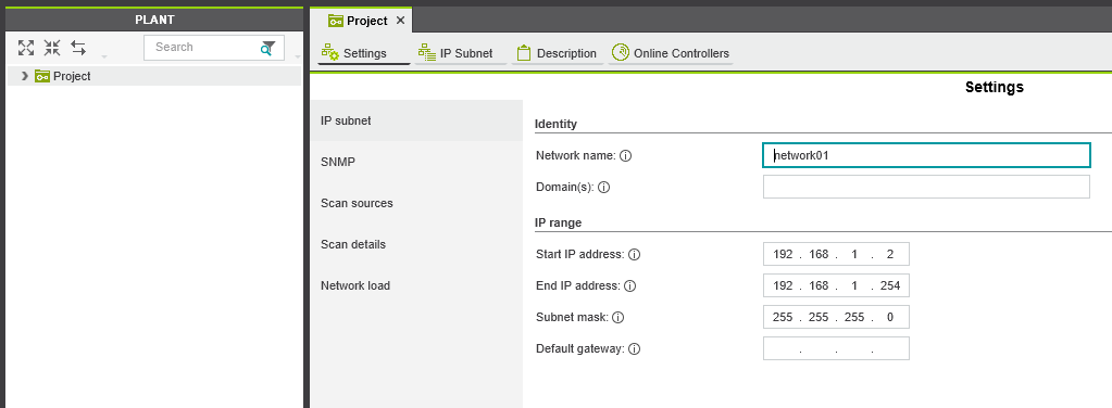
Once open, double-click on ‘Project’ on the left side to open the configurable project properties menu.
- In ‘settings’ ensure that the range includes the PLC’s default 192.168.1.10 and be sure that your PC is set to the same subnet but different IP, such as 192.168.1.20.
- In ‘Online Controllers’ choose your Ethernet adapter and click scan the network
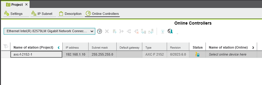
Once the PLC has been identified, right-click on the axc-f controller name on the left sidebar and ‘Logon / Logoff’. This will prompt you for the login credentials found on the controller. The default user name is ‘admin’ and the password is printed on the far top-left side of the PLCnext.
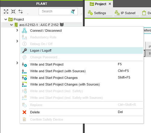
In that same menu, you can now ‘Connect/Disconnect’ to go online with the controller.
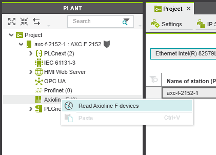
Once connected, right-click on ‘Axioline F’ and scan for modules. The list should include any modules in your current hardware setup.
Adding Variables to PLCnext
It’s fairly simple to connect variable, or tag names to I/O points. Double-click on ‘IEC 61131-3’ and open the ‘Default’ variables menu. Add names (I used a simple optical proximity switch, and I’m only using the LED on the output module to show successful program execution).
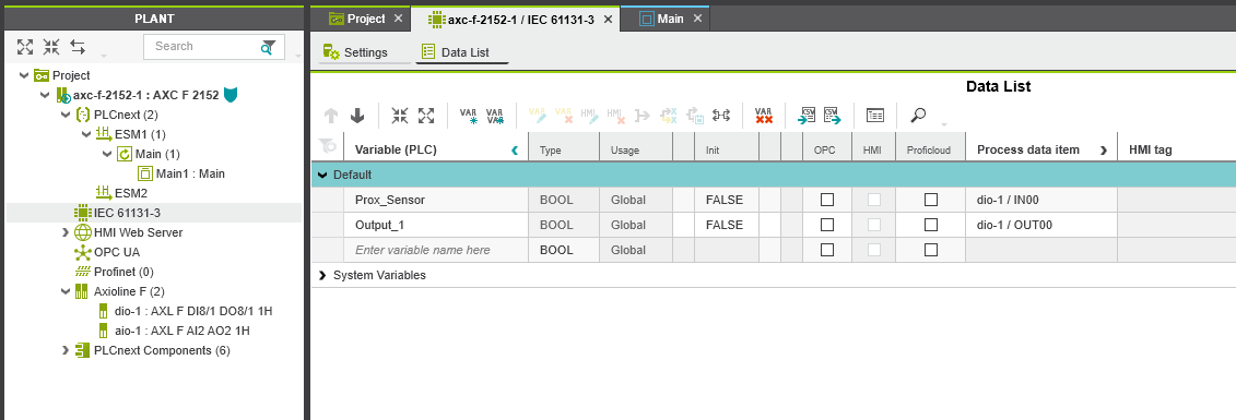
In the ‘Process data item column,’ choose IN00 for the first input terminal, and OUT00 for the first output terminal.
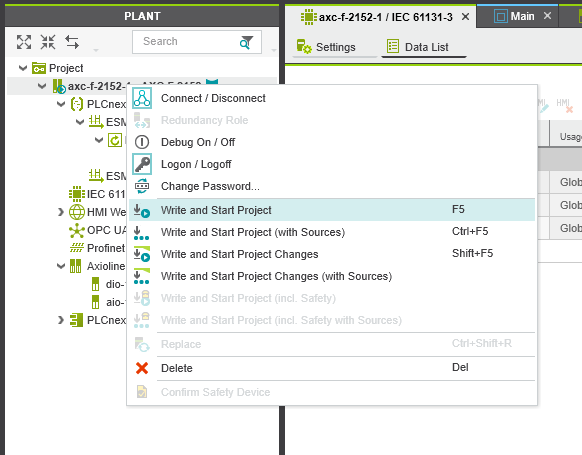
Now, it’s time to right-click on the axc-f in the project, then ‘Write and Start Project’!
After the project is sent to the controller, you can toggle the ‘Dubug On / Off’ and enter the I/O modules or the IEC 61131 and view the live status of the sensor.
Ladder Programming Time!
There’s one final step, but fortunately, this one is quite simple.
We need to write the code that will activate the output. I have chosen ladder logic due to its familiarity in the field, but all IEC 61131 languages are supported.
Open the submenu under PLCnext on the left sidebar until you reach ‘MainInstance : Main’ and double-click. We will be presented with a set of options for a programming worksheet. I have selected the ‘network-oriented ladder diagram’ or ‘NOLD’ code worksheet for my example.
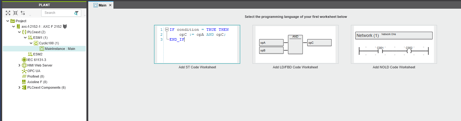
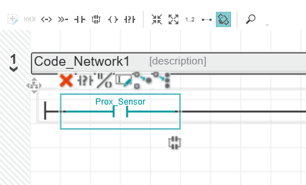
We are presented with a simple contact and coil. Each one can be assigned the variable name that we chose earlier, either by typing it directly or using the drop-down menu. We’ll choose ‘Prox_Semsor’ for the input contact and ‘Output_1’ for the coil. If you chose your variable names differently, that’s no problem, use those names.
Finally, ‘Write and Start Project’ again to begin executing your new program!
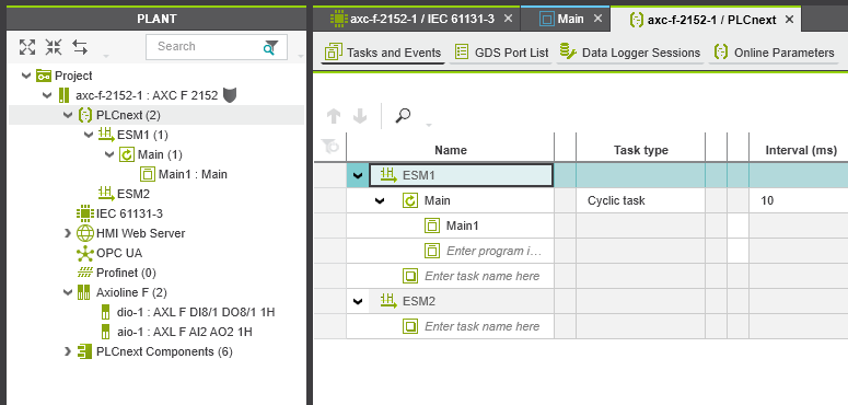
Final Notes: Cycle Times
You might notice a significant delay in the input-to-output response time, which is uncharacteristic of a PLC. Double-click on ‘PLCnext’ in the left menu and check the ‘Tasks and Events’ menu. You might find a cycle interval of 100 ms. This can be greatly reduced to create a more immediate response.
This project only serves to scratch the surface for the PLCnext platform. Once you can successfully download and execute code, a majority of the obstacles have been overcome. From this point, it’s a matter of expanding the programs to more rungs.
Later, we’ll investigate more of the IIoT capabilities of the controller to obtain greater functionality from our PLCnext platform.
All images used courtesy of the author