Facebook
 Google
 GitHub
 Linkedin
What are Six-Axis Robots?
For many manufacturing processes, Cartesian robots work well. However, there are times with a robot with more movement capabilities works better. Learn about six-axis robots, how they move, and popular applications.
Cartesian robots move on the x, y, and z-axis. It has three degrees of freedom for movement. The disadvantage of Cartesian or linear robots is that they cannot tilt or turn, but only can move along the three linear axes. When there are more degrees of freedom (also commonly referred to as the axis of movement) more versatile and precise movements can be executed by the robots. Humanoid robots like Honda ASIMO have more than 30 degrees of freedom/axis.
Having such a large number of axes is not required for most industrial operations. A large portion can be done with just three axes of Cartesian robots. SCARA provides a turning function in addition to the three-axis of Cartesian robots, for a total of four degrees of freedom. Six-axis robots have six degrees of freedom.

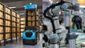
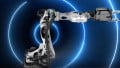
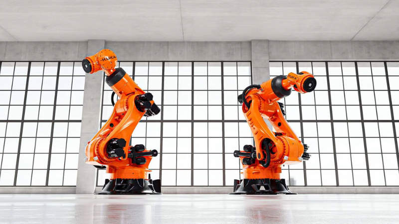
Figure 1. Aptly named six-axis robots have six degrees of freedom allowing movements Cartesian robots cannot execute. Image courtesy of Michael Jarmoluk.
These six degrees of freedom are facilitated by the servomotors present in each section. The motion control is aided by the PLCs or ICs of the robots in conjunction with compatible software. Unlike Cartesian robots that work based on only linear motion, six-axis robots have to be designed with various types of rotary motion in three-dimensional space. This makes programming the motion of these robots complex.
What Does Each Axis Do?
To design and manipulate the six-axis robots, it is important to know the roles of each axis (as well as an optional seventh). Each axis is referred to by a different name by various manufacturers. Here I’m including the names for each axis for the FANUC R - 2000iB.

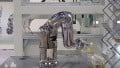
Figure 2. The six axes of the FANUC R-2000iB. Image courtesy of RobotWorx.
Although the axes may be referred to differently, the movements they perform are consistent. Let's look at each one now.
- 1st Axis: This axis is the base of the robot that can be rotated. This enables the robot arm to have a sweeping motion from left to right or right to left up to a full 180° from the central location. This axis is referred to as J1 for FANUC R-2000iB.
- 2nd Axis: This axis enables the rotation of lower robot arms to extend the rest of the arm above it forward or backward. This axis is referred to as J2 for FANUC R-2000iB.
- 3rd Axis: The 3rd axis moderates the vertical reach of the six-axis robot. The upper arm is raised or lowered with the servomotor located at this axis. Depending on the model, the upper arm can only move in the area in front of it or it can reach all the way behind the robot body. This axis is referred to as J3 for FANUC R-2000iB.
- 4th Axis: This axis works in synchronization with the fifth axis to manipulate the position of the end effector. This axis actuates a circular motion of the upper arm and the motion is commonly referred to as Wrist roll. This axis is referred to as J4 for FANUC R-2000iB.
- 5th Axis: The 5th axis performs the tilting function for the robot. Pitch and yaw motion is performed by the servomotors connected to this axis. Pitch motion is moving up and down fixed on a hinge, like opening and closing the lid of a laptop. Yaw motion is moving left and right fixed on a hinge, like opening and closing of a door. Pitch and yaw motion is the bridge between vertical and horizontal movements. This axis is referred to as J5 for FANUC R-2000iB.
- 6th Axis: Twisting motion is performed by this action. This axis is the closest one to the end effector and is responsible for its direct manipulation. This is capable of rotating more than 360° in both clockwise and anticlockwise directions. This axis is referred to as J5 for FANUC R-2000iB.
- Optional 7th Axis: This axis moves the six-axis robot linearly where it is installed. It is an optional axis that provides more functionality to the already versatile robot.
Using a Teach Pendant
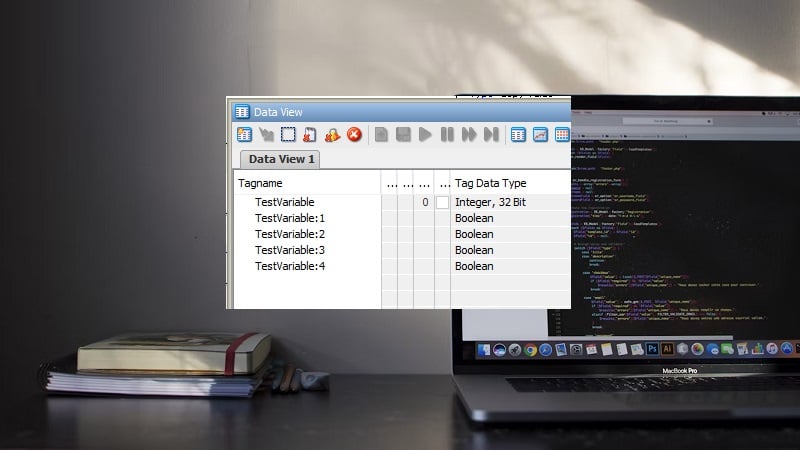
As mentioned earlier, it is quite difficult to hard code the movement to be executed. An elegant solution to this is the use of a teach pendant to “train” the robot.

Figure 3. An example of a teach pendant.
A teach pendant is a remote that can control the different axes of the six-axis robot. A human operator can use the teach pendant to move and manipulate the end of arm tooling (EoAT) for the desired operation. The robot is capable of replicating the operations the operator accomplishes with the teach pendant. If the robot needs to be repurposed, the previous operation can be erased and new operations can be taught.
Characteristics and Applications
With the six degrees of freedom in movement the six-axis robots have, they can accomplish a wide range of complex movements that Cartesian robots cannot accomplish with only linear movement. Six-axis robots can closely replicate the movement and function of the human arm making it very versatile. With this capability, it can reach under and over objects and work on surfaces linear robots cannot.
The major deficiencies of six-axis robots with respect to linear/gantry robots are precision, range, and payload capacity. While linear robots can have tolerances in the range of micrometers (μm), six-axis robots can only have tolerances in the range of millimeters (mm).
The range of gantry robots can be extended with additional scaffolding, but the range cannot be extended easily for six-axis robots. It can be done to a brief range with the addition of an extra axis of movement for the robot. This is a costly modification to robots that are already costlier than most linear robots. Six-axis robots generally have a payload-carrying capacity of 50kg. Gantry robots can have a much larger capacity at well over 100kg.
The versatility and the range of complex operations that can be accomplished by six-axis robots help it secure a spot in many modern assembly lines. Some of its applications are:
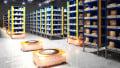
- Part picking and part handling automation
- Insert loading automation
- Stacking and sorting automation
- Packaging and palletizing automation
- Assembly cell automation
- Auxiliary operations automation
- In-mold decorating (IMD) / In-mold labeling (IML) automation
- Overmolding (press to press transfer) automation