 Facebook
 Google
 GitHub
 Linkedin
Classified Areas and Electrical Safety Measures
Any physical location in an industrial facility harboring the potential of explosion due to the presence of flammable process matter suspended in the air is called a hazardous or classified location. In this context, the label “hazardous” specifically refers to the hazard of explosion, not of other health or safety hazards.
Classified area taxonomy
In the United States, the National Electrical Code (NEC) published by the National Fire Protection Association (NFPA) defines different categories of “classified” industrial areas and prescribes safe electrical system design practices for those areas. Article 500 of the NEC categorizes classified areas into a system of Classes and Divisions. Articles 505 and 506 of the NEC provide alternative categorizations for classified areas based on Zones that is more closely aligned with European safety standards.
The Class and Division taxonomy defines classified areas in terms of hazard type and hazard probability. Each “Class” contains (or may contain) different types of potentially explosive substances: Class I is for gases or vapors, Class II is for combustible dusts, and Class III is for flammable fibers. The three-fold class designation is roughly scaled on the size of the flammable particles, with Class I being the smallest (gas or vapor molecules) and Class III being the largest (fibers of solid matter). Each “Division” ranks a classified area according to the likelihood of explosive gases, dusts, or fibers being present. Division 1 areas are those where explosive concentrations can or do exist under normal operating conditions. Division 2 areas are those where explosive concentrations only exist infrequently or under abnormal conditions.
The “Zone” method of area classifications defined in Article 505 of the National Electrical Code applies to Class I (explosive gas or vapor) applications, but the three-fold Zone ranks (0, 1, and 2) are analogous to Divisions in their rating of explosive concentration probabilities. Zone 0 defines areas where explosive concentrations are continually present or normally present for long periods of time. Zone 1 defines areas where those concentrations may be present under normal operating conditions, but not as frequently as Zone 0. Zone 2 defines areas where explosive concentrations are unlikely under normal operating conditions, and when present do not exist for substantial periods of time. This three-fold Zone taxonomy may be thought of as expansion on the two-fold Division system, where Zones 0 and 1 are sub-categories of Division 1 areas, and Zone 2 is nearly equivalent to a Division 2 area. A similar three-zone taxonomy for Class II and Class III applications is defined in Article 506 of the National Electrical Code, the zone ranks for these dust and fiber hazards numbered 20, 21, and 22 (and having analogous meanings to zones 0, 1, and 2 for Class I applications).
An example of a classified area common to most peoples’ experience is a vehicle refueling station. Being a (potentially) explosive vapor, the hazard in question here is deemed Class I. The Division rating varies with proximity to the fume source. For an upward-discharging vent pipe from an underground gasoline storage tank, the area is rated as Division 1 within 900 millimeters (3 feet) from the vent hole. Between 3 feet and 5 feet away from the vent, the area is rated as Division 2. In relation to an outdoor fuel pump (dispenser), the space internal to the pump enclosure is rated Division 1, and any space up to 18 inches from grade level and up to 20 feet away (horizontally) from the pump is rated Division 2.
Within Class I and Class II (but not Class III), the National Electrical Code further sub-divides hazards according to explosive properties called Groups. Each group is defined either according to a substance type, or according to specific ignition criteria. Ignition criteria listed in the National Electrical Code (Article 500) include the maximum experimental safe gap (MESG) and the minimum ignition current ratio (MICR). The MESG is based on a test where two hollow hemispheres separated by a small gap enclose both an explosive air/fuel mixture and an ignition source. Tests are performed with this apparatus to determine the maximum gap width between the hemispheres that will not permit the excursion of flame from an explosion within the hemispheres triggered by the ignition source. The MICR is the ratio of electrical ignition current for an explosive air/fuel mixture compared to an optimum mixture of methane and air. The smaller of either these two values, the more dangerous the explosive substance is.
Class I substances are grouped according to their respective MESG and MICR values, with typical gas types given for each group:
| Group | Typical substance | Safe gap | Ignition current |
|---|---|---|---|
| A | Acetylene | ||
| B | Hydrogen | MESG \(\leq\) 0.45 mm | MICR \(\leq\) 0.40 |
| C | Ethylene | 0.45 mm \(\lt\) MESG \(\leq\) 0.75 mm | 0.40 \(\lt\) MICR \(\leq\) 0.80 |
| D | Propane | 0.75 mm \(\lt\) MESG | 0.80 \(\lt\) MICR |
Class II substances are grouped according to material type:
| Group | Substances |
|---|---|
| E | Metal dusts |
| F | Carbon-based dusts |
| G | Other dusts (wood, grain, flour, plastic, etc.) |
Just to make things confusing, the Class/Zone system described in NEC Article 505 uses a completely different lettering order to describe gas and vapor groups (at the time of this writing there is no grouping of dust or fiber types for the zone system described in Article 506 of the NEC):
| Group | Typical substance(s) | Safe gap<\th> | Ignition current |
|---|---|---|---|
| IIC | Acetylene, Hydrogen | MESG \(\leq\) 0.50 mm | MICR \(\leq\) 0.45 |
| IIB | Ethylene | 0.50 mm \(\lt\) MESG $\leq\) 0.90 mm | 0.45 \(\lt\) MICR \(\leq\) 0.80 |
| IIA | Acetone, Propane | 0.90 mm \(\lt\) MESG | 0.80 \(\lt\) MICR |
Explosive limits
In order to have combustion (an explosion being a particularly aggressive form of combustion), certain basic criteria must be satisfied: a proper oxidizer/fuel ratio, sufficient energy for ignition, and the potential for a self-sustaining chemical reaction (i.e. the absence of any chemical inhibitors). We may show these criteria in the form of a fire triangle, the concept being that removing any of these three critical elements renders a fire (or explosion) impossible:
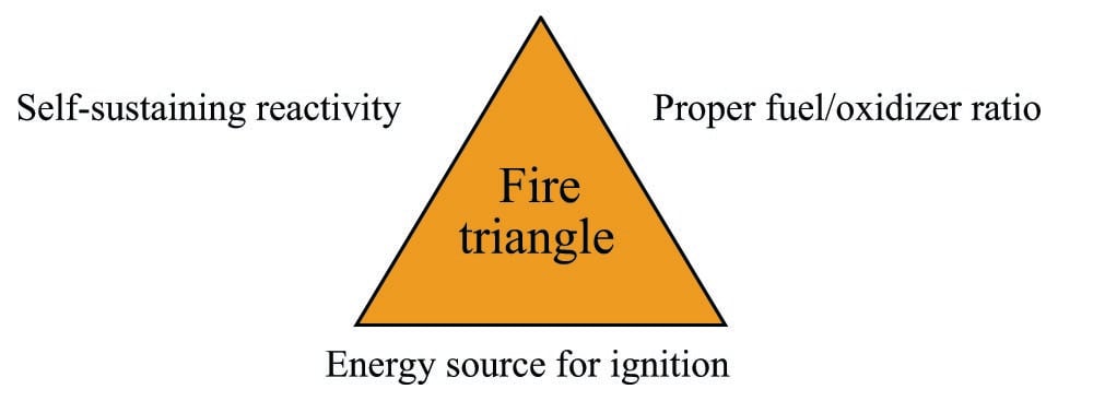
The fire triangle serves as a qualitative guide for preventing fires and explosions, but it does not give sufficient information to tell us if the necessary conditions exist to support a fire or explosion. In order for a fire or explosion to occur, we need to have an adequate mixture of fuel and oxidizer in the correct proportions, and a source of ignition energy exceeding a certain minimum threshold.
Suppose we had a laboratory test chamber filled with a mixture of acetone vapor (70% by volume) and air at room temperature, with an electrical spark gap providing convenient ignition. No matter how energetic the spark, this mixture would not explode, because there is too rich a mixture of acetone (i.e. too much acetone mixed with not enough air). Every time the spark gap discharges, its energy would surely cause some acetone molecules to combust with available oxygen molecules. However, since the air is so dilute in this rich acetone mixture, those scarce oxygen molecules are depleted fast enough that the flame temperature quickly falls off and is no longer hot enough to trigger the remaining oxygen molecules to combust with the plentiful acetone molecules.
The same problem occurs if the acetone/air mixture is too lean (not enough acetone and too much air). This is what would happen if we diluted the acetone vapors to a volumetric concentration of only 0.5% inside the test chamber: any spark at the gap would indeed cause some acetone molecules to combust, but there would be too few available to support expansive combustion across the rest of the chamber.
We could also have an acetone/air mixture in the chamber ideal for combustion (about 9.5% acetone by volume) and still not have an explosion if the spark’s energy were insufficient. Most combustion reactions require a certain minimum level of activation energy to overcome the potential barrier before molecular bonding between fuel atoms and oxidizer atoms occurs. Stated differently, many combustion reactions are not spontaneous at room temperature and at atmospheric pressure – they need a bit of “help” to initiate.
All the necessary conditions for an explosion (assuming no chemical inhibitors are present) may be quantified and plotted as an ignition curve for any particular fuel and oxidizer combination. This next graph shows an ignition curve for an hypothetical fuel gas mixed with air:

Note how any point in the chart lying above the curve is “dangerous,” while any point below the curve is “safe.” The three critical values on this graph are the Lower Explosive Limit (LEL), the Upper Explosive Limit (UEL), and the Minimum Ignition Energy (MIE). These critical values differ for every type of fuel and oxidizer combination, change with ambient temperature and pressure, and may be rendered irrelevant in the presence of a catalyst (a chemical substance that works to promote a reaction without itself being consumed by the reaction). Most ignition curves are published with the assumed conditions of air as the oxidizer, at room temperature and atmospheric pressure, with no catalyst(s) present.
Some substances are so reactive that their minimum ignition energy (MIE) levels are well below the thermal energy of ambient air temperatures. Such fuels will auto-ignite the moment they come into contact with air, which effectively means one cannot prevent a fire or explosion by eliminating sources of flame or sparks. When dealing with such substances, the only means for preventing fires and explosions lies with maintaining fuel/air ratios outside of the danger zone (i.e. below the LEL or above the UEL), or by using a chemical inhibitor to prevent a self-sustaining reaction.
The greater the difference in LEL and UEL values, the greater “explosive potential” a fuel gas or vapor presents (all other factors being equal), because it means the fuel may explode over a wider range of mixture conditions. It is instructive to research the LEL and UEL values for many common substances, just to see how “explosive” they are relative to each other:
| Substance | LEL % volume | UEL % volume |
|---|---|---|
| Acetylene | 2.5% | 100% |
| Acetone | 2.5% | 12.8% |
| Butane | 1.5% | 8.5% |
| Carbon disulfide | 1.3% | 50% |
| Carbon monoxide | 12.5% | 74% |
| Ether | 1.9% | 36% |
| Ethylene oxide | 2.6% | 100% |
| Gasoline | 1.4% | 7.6% |
| Kerosene | 0.7% | 5% |
| Hydrazine | 2.9% | 98% |
| Hydrogen | 4.0% | 74.2% |
| Methane | 4.4% | 17% |
| Propane | 2.1% | 9.5% |
Note how both acetylene and ethylene oxide have UEL values of 100%. This means it is possible for these gases to explode even when there is no oxidizer present. Some other chemical substances exhibit this same property (n-propyl nitrate being another example), where the lack of an oxidizer does not prevent an explosion. With these substances in high concentration, our only practical hope of avoiding explosion is to eliminate the possibility of an ignition source in its presence. Some substances have UEL values so high that the elimination of oxidizers is only an uncertain guard against combustion: hydrazine being one example with a UEL of 98%, and diborane being another example with a UEL of 88%.
Protective measures
Different strategies exist to help prevent electrical devices from triggering fires or explosions in classified areas. These strategies may be broadly divided four ways:
- Contain the explosion: enclose the device inside a very strong box that contains any explosion generated by the device so as to not trigger a larger explosion outside the box. This strategy may be viewed as eliminating the “ignition” component of the fire triangle, from the perspective of the atmosphere outside the explosion-proof enclosure (ensuring the explosion inside the enclosure does not ignite a larger explosion outside).
- Shield the device: enclose the electrical device inside a suitable box or shelter, then purge that enclosure with clean air (or a pure gas) that prevents an explosive mixture from forming inside the enclosure. This strategy works by eliminating the “proper fuel/oxidizer ratio” component of the fire triangle: by eliminating fuel (if purged by air), or by eliminating oxidizer (if purged by fuel gas), or by eliminating both (if purged by an inert gas).
- Encapsulated design: manufacture the device so that it is self-enclosing. In other words, build the device in such a way that any spark-producing elements are sealed air-tight within the device from any explosive atmosphere. This strategy works by eliminating the “ignition” component of the fire triangle (from the perspective of outside the device) or by eliminating the “proper fuel/oxidizer ratio” component (from the perspective of inside the device).
- Limit total circuit energy: design the circuit such that there is insufficient energy to trigger an explosion, even in the event of an electrical fault. This strategy works by eliminating the “ignition” component of the fire triangle.
It should be noted that any one of these strategies, correctly and thoroughly applied, is sufficient to mitigate the risk of fire and explosion. For this reason you will seldom see more than one of these strategies simultaneously applied (e.g. an explosion-proof enclosure housing a circuit with insufficient energy to trigger an explosion).
A common example of the first strategy is to use extremely rugged metal explosion-proof (NEMA 7 or NEMA 8) enclosures instead of the more common sheet-metal or fiberglass enclosures to house electrical equipment. Two photographs of explosion-proof electrical enclosures reveal their unusually rugged construction:
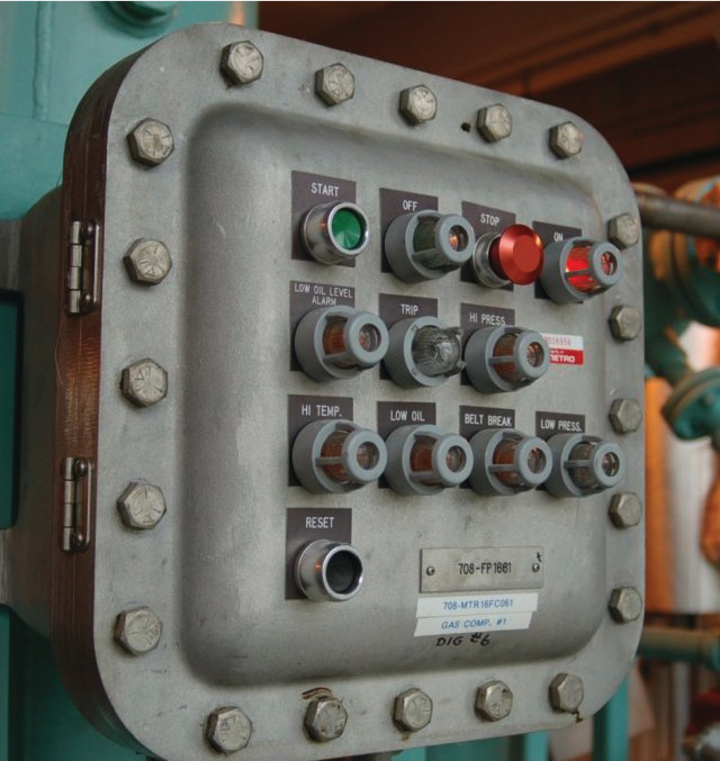
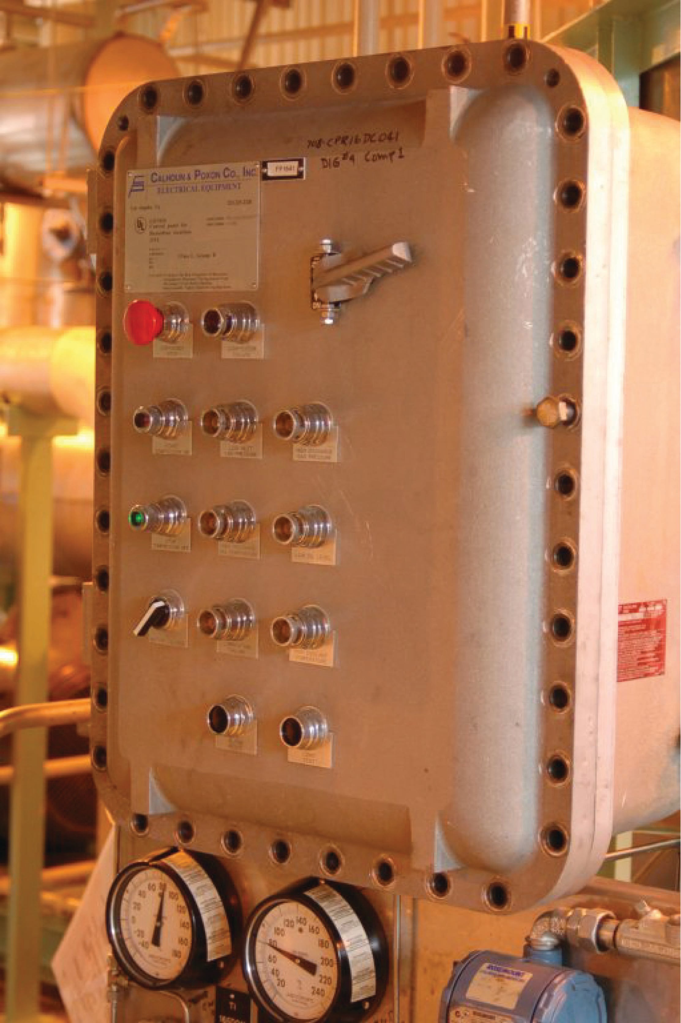
Note the abundance of bolts securing the covers of these enclosures! This is necessary in order to withstand the enormous forces generated by the pressure of an explosion developing inside the enclosure. Note also how most of the bolts have been removed from the door of the right-hand enclosure. This is an unsafe and very unfortunate occurrence at many industrial facilities, where technicians leave just a few bolts securing the cover of an explosion-proof enclosure because it is so time-consuming to remove all of them to gain access inside the enclosure for maintenance work. Such practices negate the safety of the explosion-proof enclosure, rendering it just as dangerous as a sheet metal enclosure in a classified area.
Explosion-proof enclosures are designed in such a way that high-pressure gases resulting from an explosion within the enclosure must pass through small gaps (either holes in vent devices, and/or the gap formed by a bulging door forced away from the enclosure box) en route to exiting the enclosure. As hot gases pass through these tight metal gaps, they are forced to cool to the point where they will not ignite explosive gases outside the enclosure, thus preventing the original explosion inside the enclosure from triggering a far more violent event. This is the same phenomenon measured in determinations of MESG (Maximum Experimental Safe Gap) for an explosive air/fuel mixture. With an explosion-proof enclosure, all gaps are designed to be less than the MESG for the mixtures in question.
A similar strategy involves the use of a non-flammable purge gas pressurizing an ordinary electrical enclosure such that explosive atmospheres are prevented from entering the enclosure. Ordinary compressed air may be used as the purge gas, so long as provisions are made to ensure the air compressor supplying the compressed air is in a non-classified area where explosive gases will never be drawn into the compressed air system.
Devices may be encapsulated in such a way that explosive atmospheres cannot penetrate the device to reach anything generating sufficient spark or heat. Hermetically sealed devices are an example of this protective strategy, where the structure of the device has been made completely fluid-tight by fusion joints of its casing. Mercury tilt-switches are good examples of such electrical devices, where a small quantity of liquid mercury is hermetically sealed inside a glass tube. No outside gases, vapors, dusts, or fibers can ever reach the spark generated when the mercury comes into contact (or breaks contact with) the electrodes:


The ultimate method for ensuring instrument circuit safety in classified areas is to intentionally limit the amount of energy available within a circuit such that it cannot generate enough heat or spark to ignite an explosive atmosphere, even in the event of an electrical fault within the circuit. Article 504 of the National Electrical Code specifies standards for this method. Any system meeting these requirements is called an intrinsically safe or I.S. system. The word “intrinsic” implies that the safety is a natural property of the circuit, since it lacks even the ability to produce an explosion-triggering spark.
One way to underscore the meaning of intrinsic safety is to contrast it against a different concept that has the appearance of similarity. Article 500 of the National Electrical Code defines nonincendive equipment as devices incapable of igniting a hazardous atmosphere under normal operating conditions. However, the standard for nonincendive devices or circuits does not guarantee what will happen under abnormal conditions, such as an open- or short-circuit in the wiring. So, a “nonincendive” circuit may very well pose an explosion hazard, whereas an “intrinsically safe” circuit will not because the intrinsically safe circuit simply does not possess enough energy to trigger an explosion under any electrical fault condition. As a result, nonincendive circuits are not approved in Class I or Class II Division 1 locations whereas intrinsically safe circuits are approved for all hazardous locations.
Most modern 4 to 20 mA analog signal instruments may be used as part of intrinsically safe circuits so long as they are connected to control equipment through suitable safety barrier interfaces, the purpose of which is to limit the amount of voltage and current available at the field device to low enough levels that an explosion-triggering spark is impossible even under fault conditions (e.g. a short-circuit in the field instrument or wiring). A simple intrinsic safety barrier circuit made from passive components is shown in the following diagram:
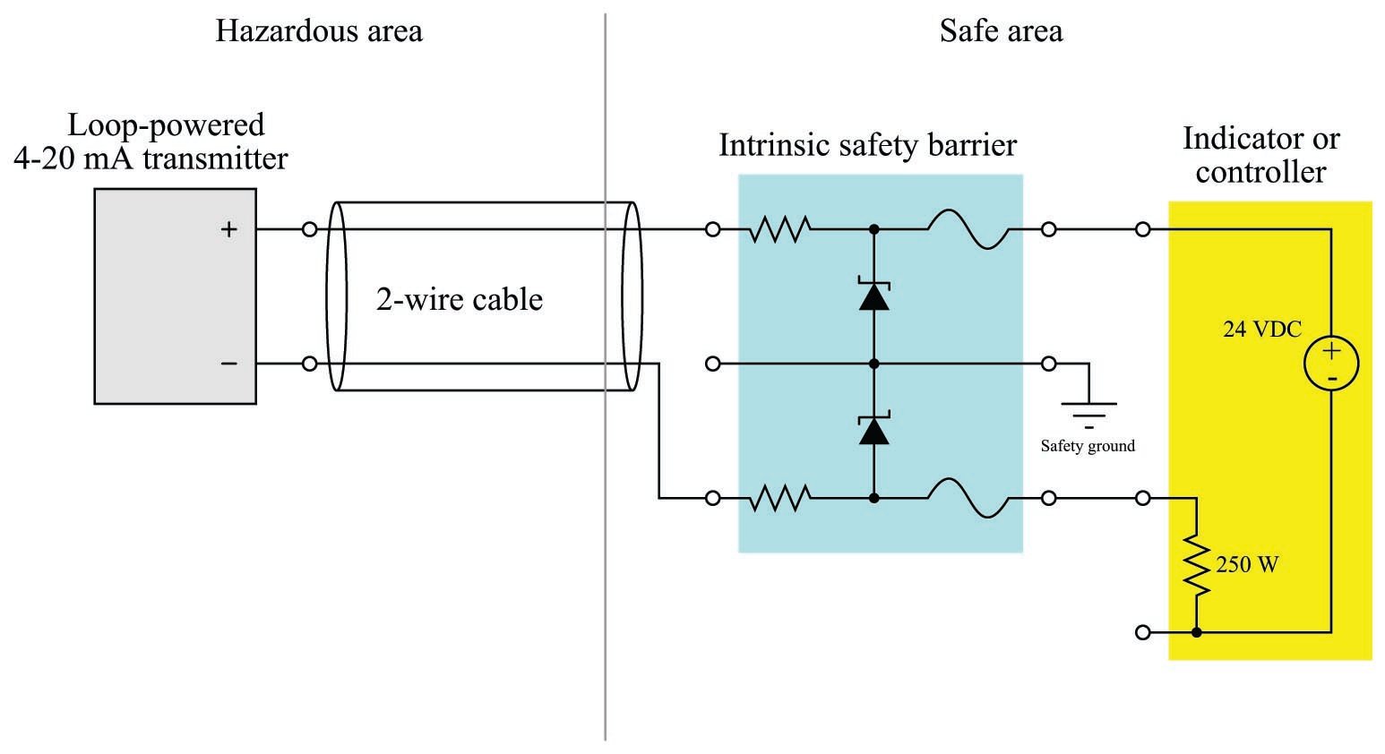
In normal operation, the 4-20 mA field instrument possesses insufficient terminal voltage and insufficient loop current to pose any threat of hazardous atmosphere ignition. However, the normally modest voltage and current values within a healthy 4-20 mA loop circuit are enough for that circuit to be considered intrinsically safe. In order to be intrinsically safe, the circuit’s voltage and current levels must be limited even in the event of device or wiring faults. This is the purpose of the intrinsic safety barrier circuit: to serve as a safeguard in the event of unforseen wiring and/or component faults so that there is no possible way for enough voltage or current to develop to trigger an explosion.
If a short-circuit develops in the field instrument, the series resistance of the barrier circuit will limit fault current to a value low enough not to pose a threat in the hazardous area. If something fails in the receiving instrument to cause a much greater power supply voltage to develop at its terminals, the zener diode inside the barrier will break down and provide a shunt path for fault current that bypasses the field instrument (and may possibly blow the fuse in the barrier). Thus, the intrinsic safety barrier circuit provides protection against overcurrent and overvoltage faults, so that neither type of fault will result in enough electrical energy available at the field device to ignite an explosive atmosphere.
A photograph of an MTL-brand intrinsic safety barrier is shown here. A schematic diagram on the side of this barrier shows its internal circuitry:

Note that a barrier device such as this must be present in the 4-20 mA analog circuit in order for the circuit to be intrinsically safe. The “intrinsic” safety rating of the circuit depends on this barrier, not on the integrity of the field device or of the receiving device. Without this barrier in place, the instrument circuit is not intrinsically safe, even though the normal operating voltage and current parameters of the field and receiving devices are well within the parameters of safety for classified areas. It is the barrier and the barrier alone which guarantees those voltage and current levels will remain within safe limits in the event of abnormal circuit conditions such as a field wiring short, field device fault, or a faulty loop power supply.
More sophisticated active barrier devices are manufactured which provide electrical isolation from ground in the instrument wiring, thus eliminating the need for a safety ground connection at the barrier device.

In the example shown here, transformers are used to electrically isolate the analog current signal so that there is no path for DC fault current between the field instrument and the receiving instrument, ground or no ground.
Safety barrier circuits fundamentally limit the amount of power deliverable to a field device from a power supply located in the safe area. Barrier circuits cannot, however, ensure safety for field devices capable of generating their own electrical energy. In order for such devices to be considered intrinsically safe, their natural abilities for generating voltage, current, and power must fall below limits defined in NEC article 504. Sensors such as pH electrodes, thermocouples, and photovoltaic light detectors are examples of such field devices, and are called simple apparatus by the NEC. The qualifications for a generating device to be a “simple apparatus” is that it cannot generate more than 1.5 volts of voltage, and more than 100 milliamps of current, and more than 25 milliwatts of power. If a device’s ability to generate electricity exceeds these limits, the device is not a “simple apparatus” and therefore its circuit is not intrinsically safe.
An example of a generating field device exceeding these limits is a tachogenerator: a small DC generator used to measure the speed of rotating equipment by outputting a DC voltage proportional to speed (typically over a 0-10 volt range). An alternative to a tachogenerator for measuring machine speed is an optical encoder, using a slotted wheel to chop a light beam (from an LED), generating a pulsed electrical signal of sufficiently low intensity to qualify as a simple apparatus.
Passive (non-generating) field devices may also be classified as “simple apparatus” if they do not dissipate more than 1.3 watts of power. Examples of passive, simple apparatus include switches, LED indicator lamps, and RTD (Resistive Temperature Detector) sensors. Even devices with internal inductance and/or capacitance may be deemed “simple apparatus” if their stored energy capacity is insufficient to pose a hazard.
In addition to the use of barrier devices to create an intrinsically safe circuit, the National Electrical Code (NEC) article 504 specifies certain wiring practices different from normal control circuits. The conductors of an intrinsically safe circuit (i.e. conductors on the “field” side of a barrier) must be separated from the conductors of the non-intrinsically safe circuit (i.e. conductors on the “supply” side of the barrier) by at least 50 millimeters, which is approximately 2 inches. Conductors must be secured prior to terminals in such a way that they cannot come into contact with non-intrinsically safe conductors if the terminal becomes loose. Also, the color light blue may be used to identify intrinsically safe conductors, raceways, cable trays, and junction boxes so long as that color is not used for any other wiring in the system.
