 Facebook
 Google
 GitHub
 Linkedin
On/off Electric Motor Control Circuits
An electric motor is often used as a discrete control element in a control system if driving a pump, conveyor belt, or other machines for the transportation of a process substance. As such, it is important to understand the functioning of motor control circuits.
Of all the available electric motor types, the most common found in industrial applications (by far) is the three-phase AC induction motor. For this reason, this section of the book will focus exclusively on this type of motor as a final control element.
AC induction motors
The basic principle of an AC induction motor is that one or more out-of-phase AC (sinusoidal) currents energize sets of electromagnet coils (called stator coils or windings) arranged around the circumference of a circle. As these currents alternately energize the coils, a magnetic field is produced which “appears” to rotate around the circle. This rotating magnetic field is not unlike the appearance of motion produced by an array of chaser lights blinking on and off in sequence: although the bulbs themselves are stationary, the out-of-phase sequence of their on-and-off blinking makes it appear as though a pattern of light “moves” or “chases” along the length of the array. Likewise, the superposition of magnetic fields created by the out-of-phase coils resembles a magnetic field of constant intensity revolving around the circle. The following images show how the magnetic field vector (the red arrow) is generated by a superposition of magnetic poles through one complete cycle (1 revolution), viewing the images from left to right, top to bottom (the same order as you would read words in an English sentence):
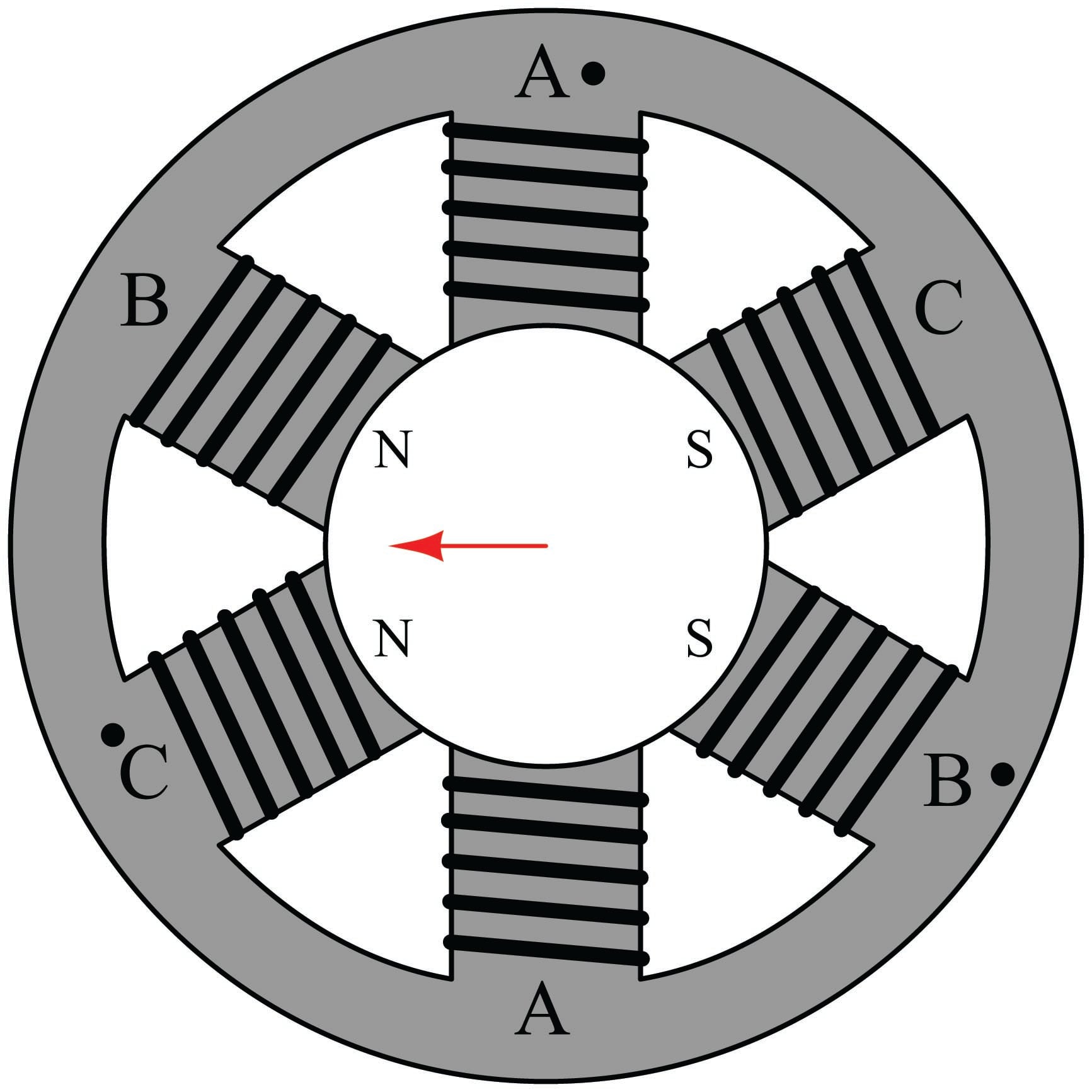
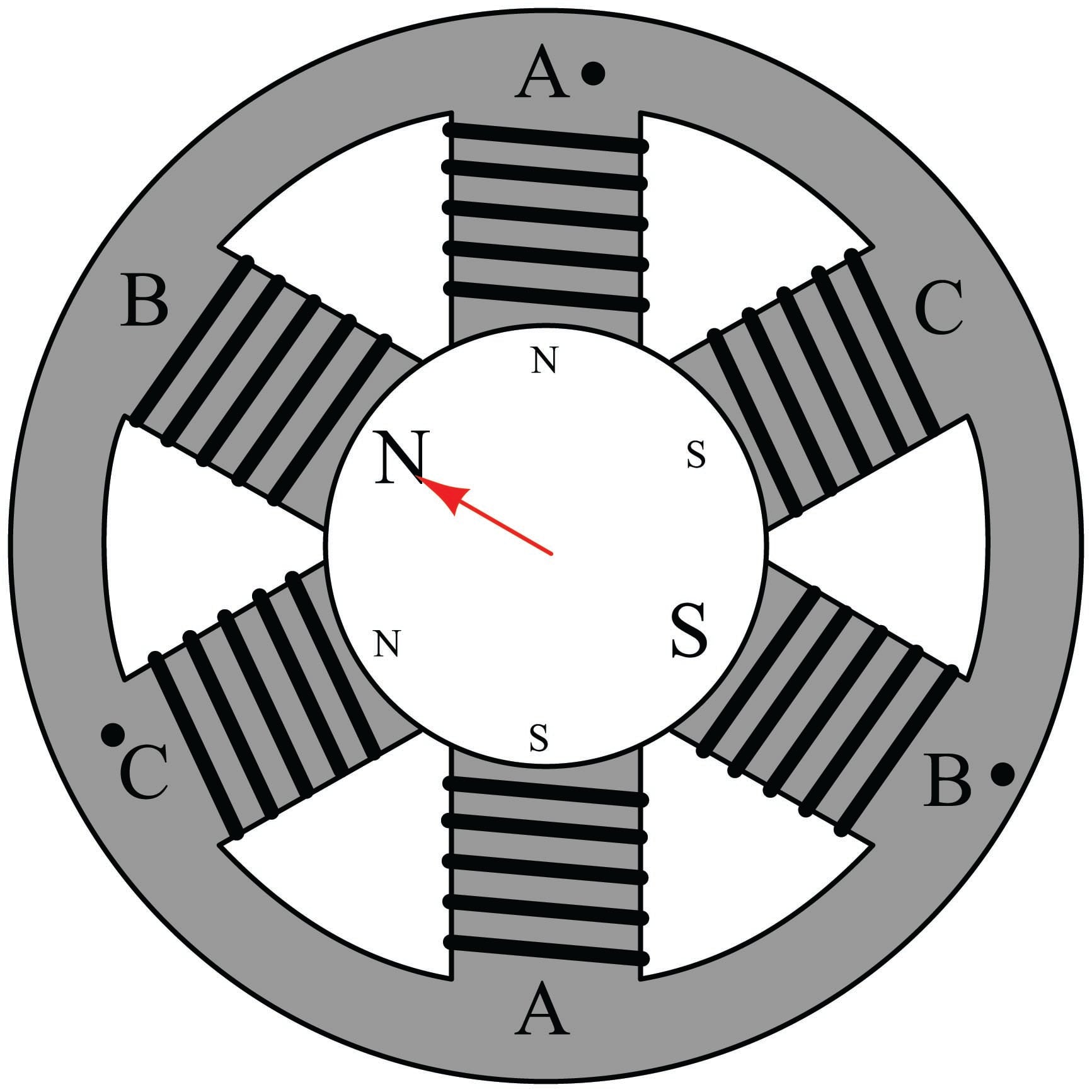
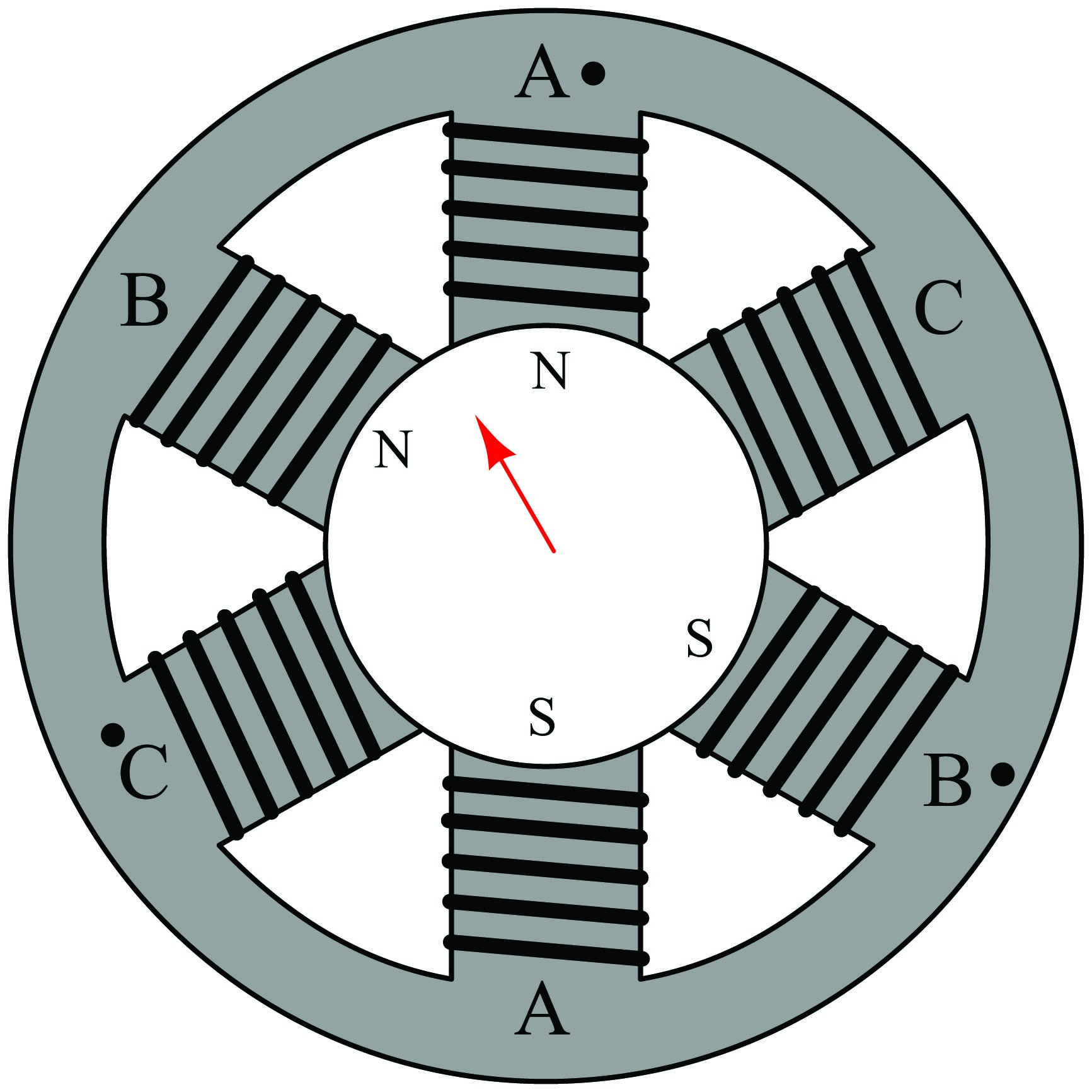
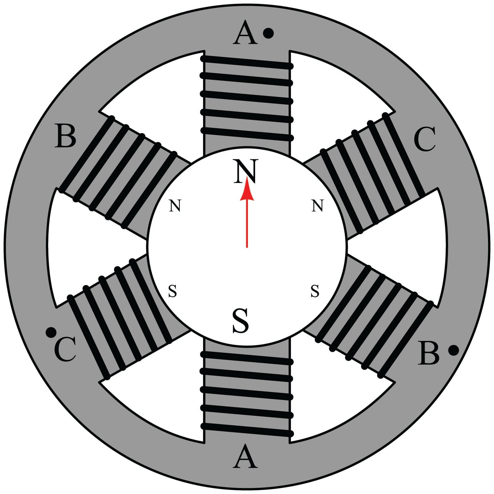
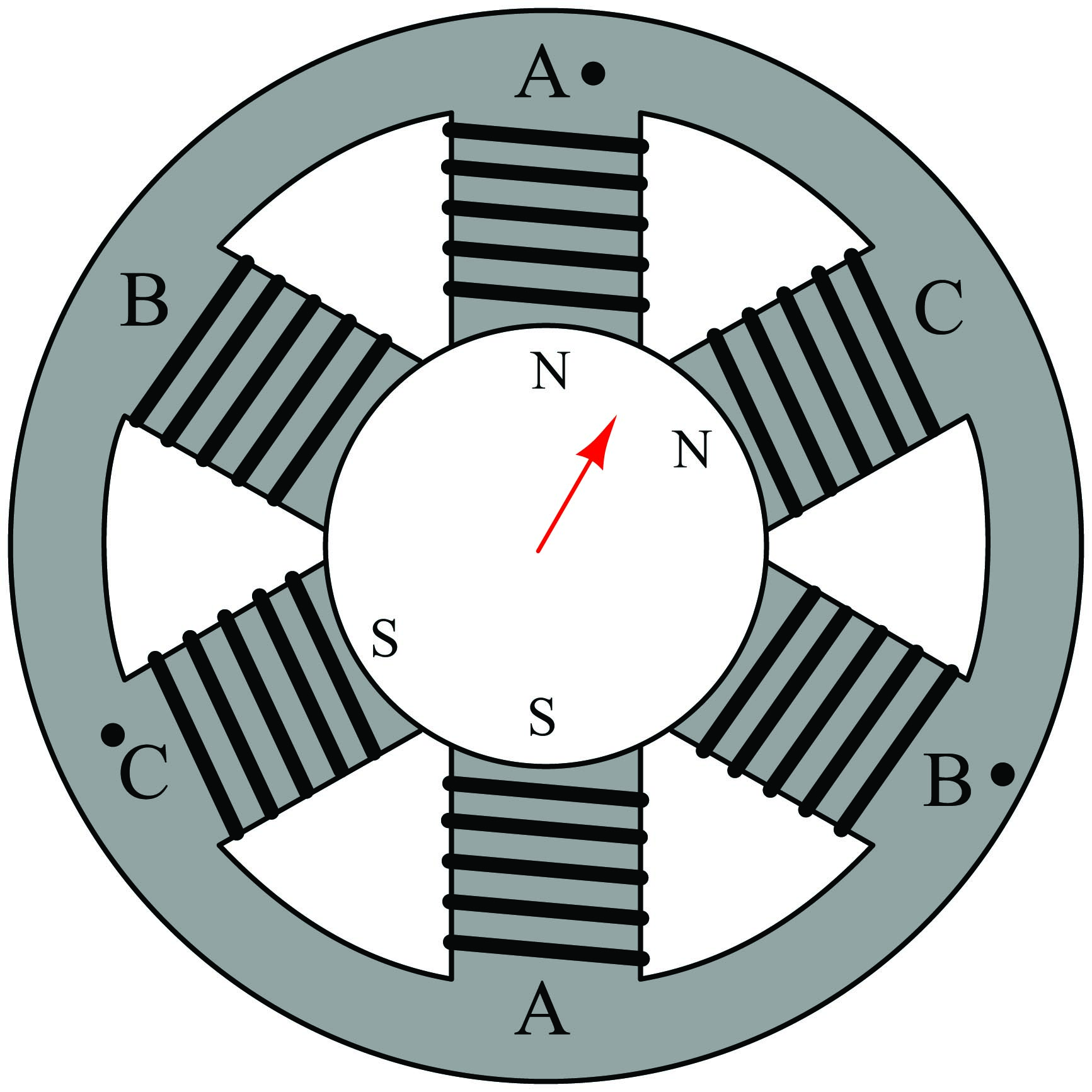
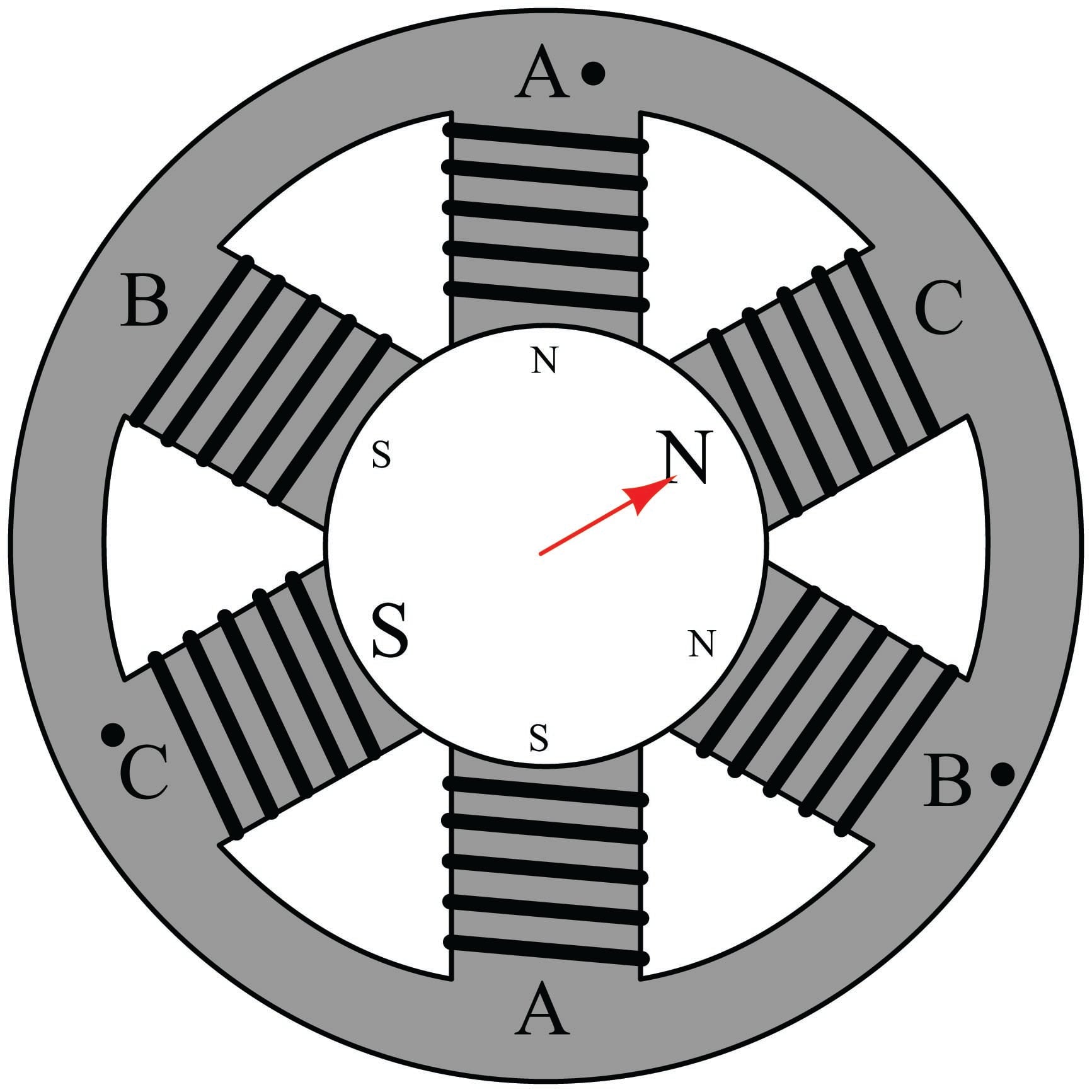
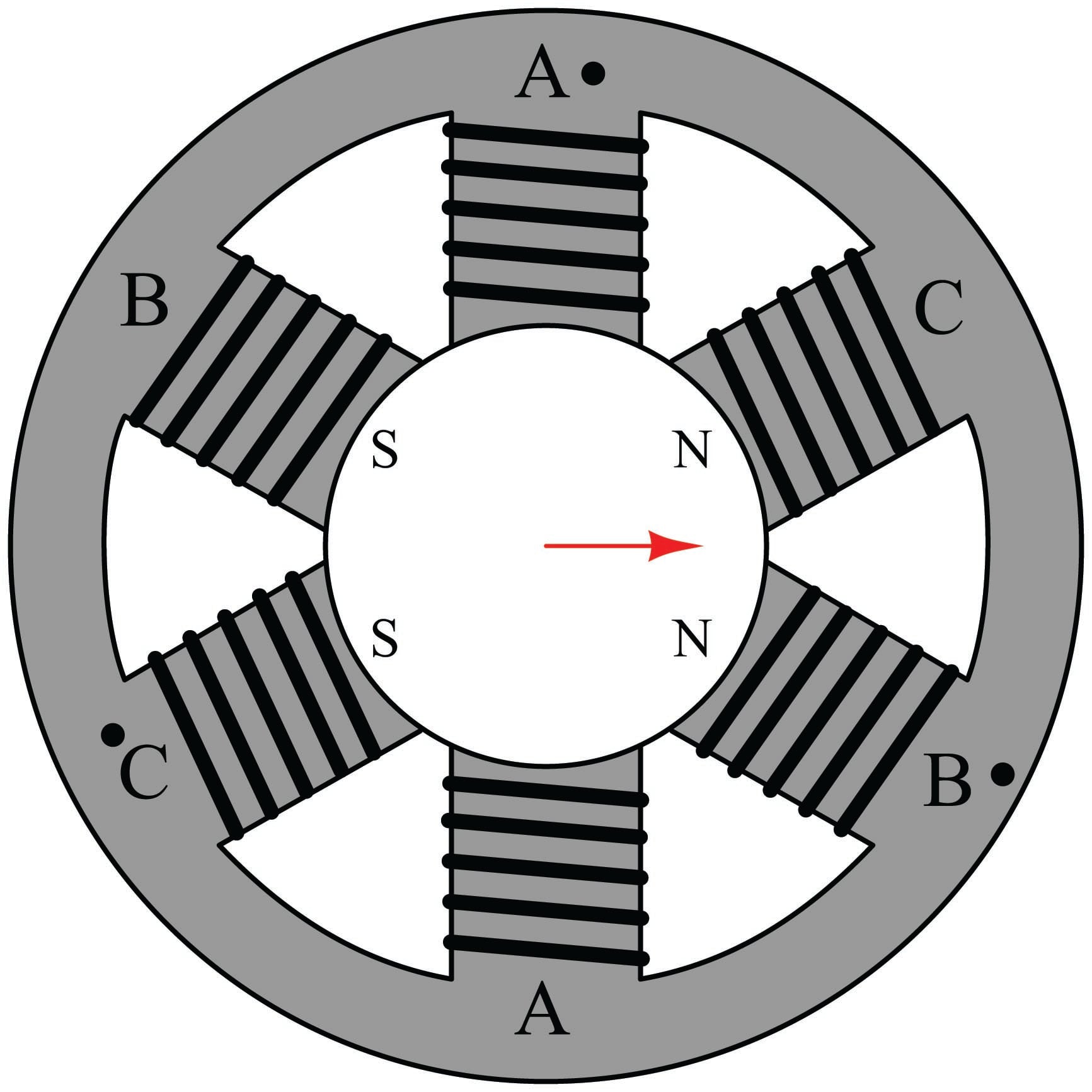
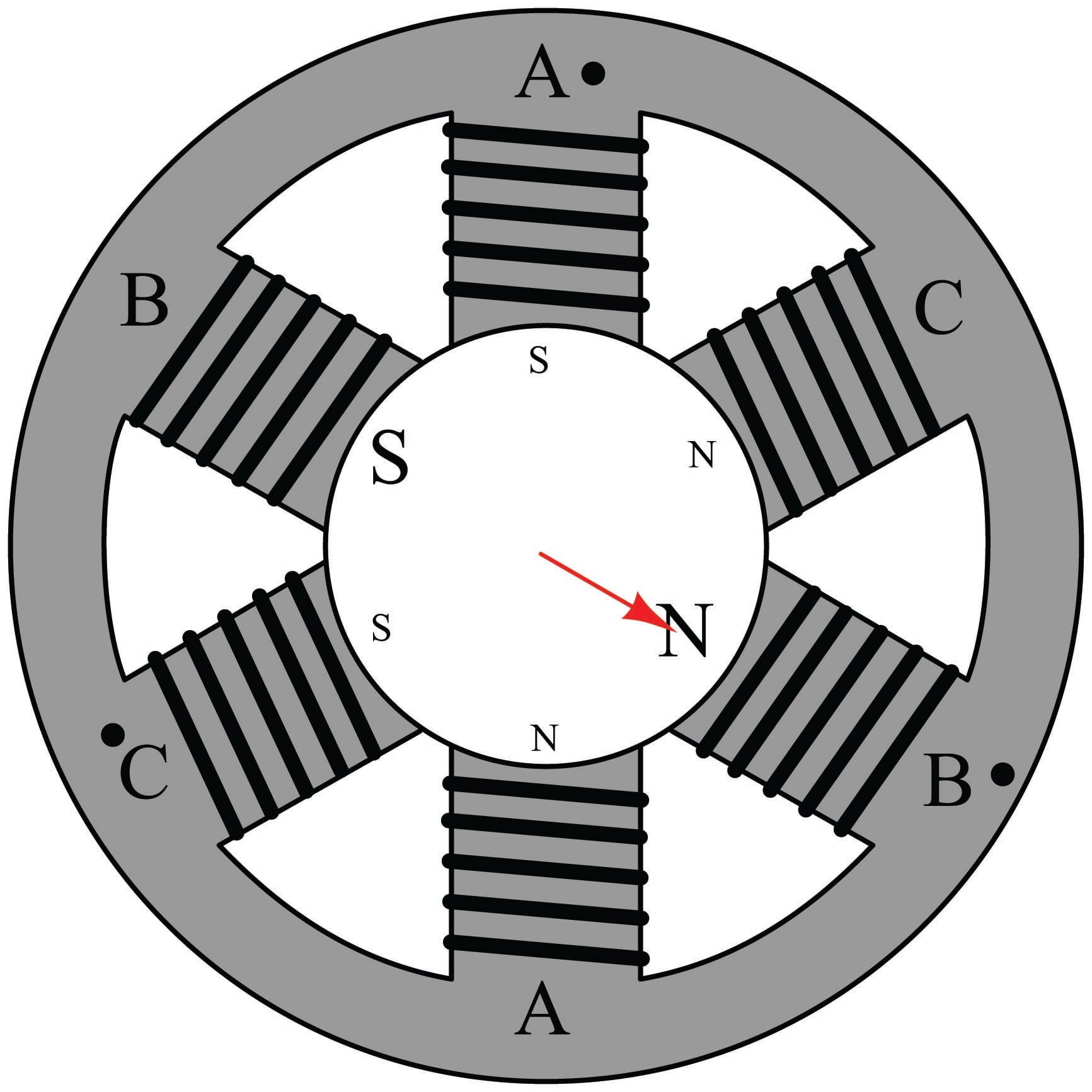
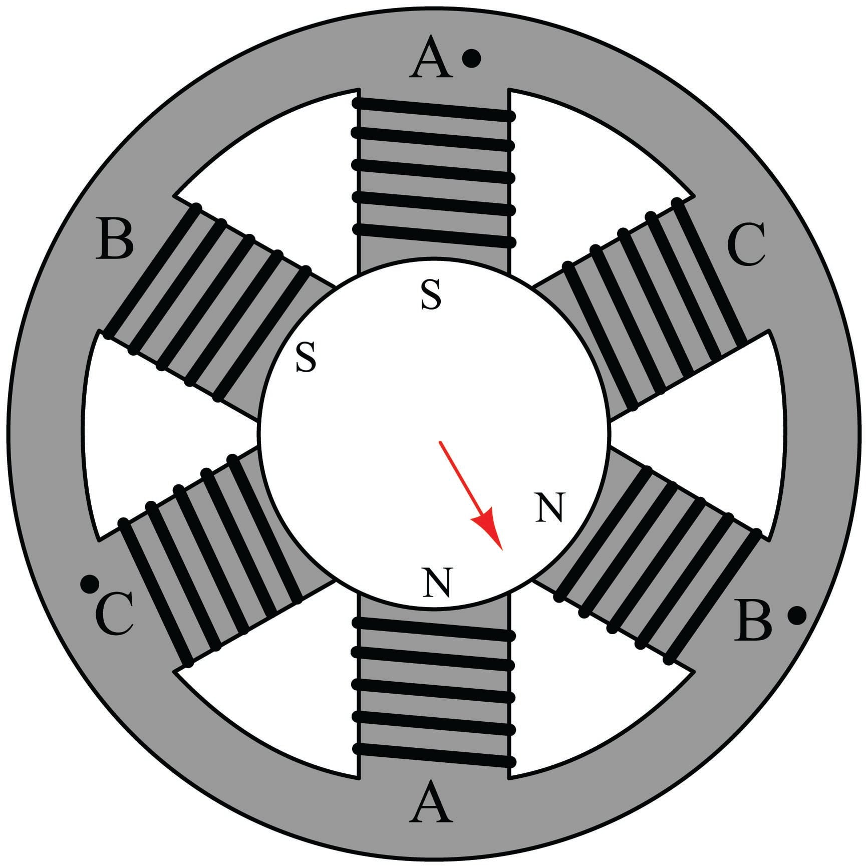
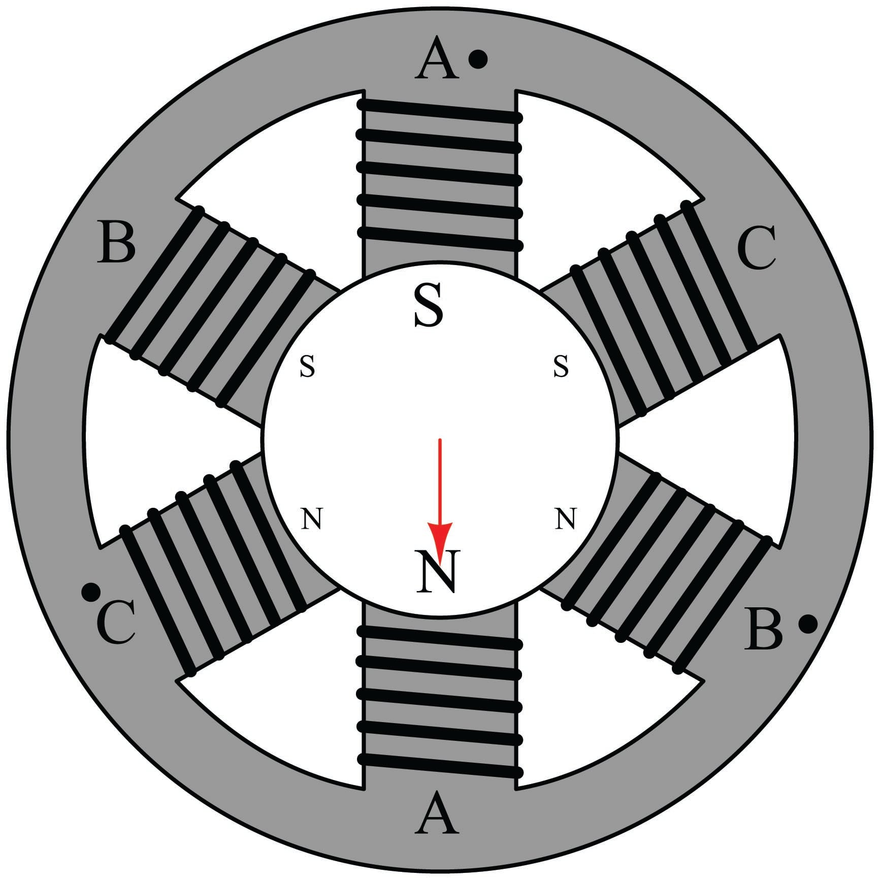
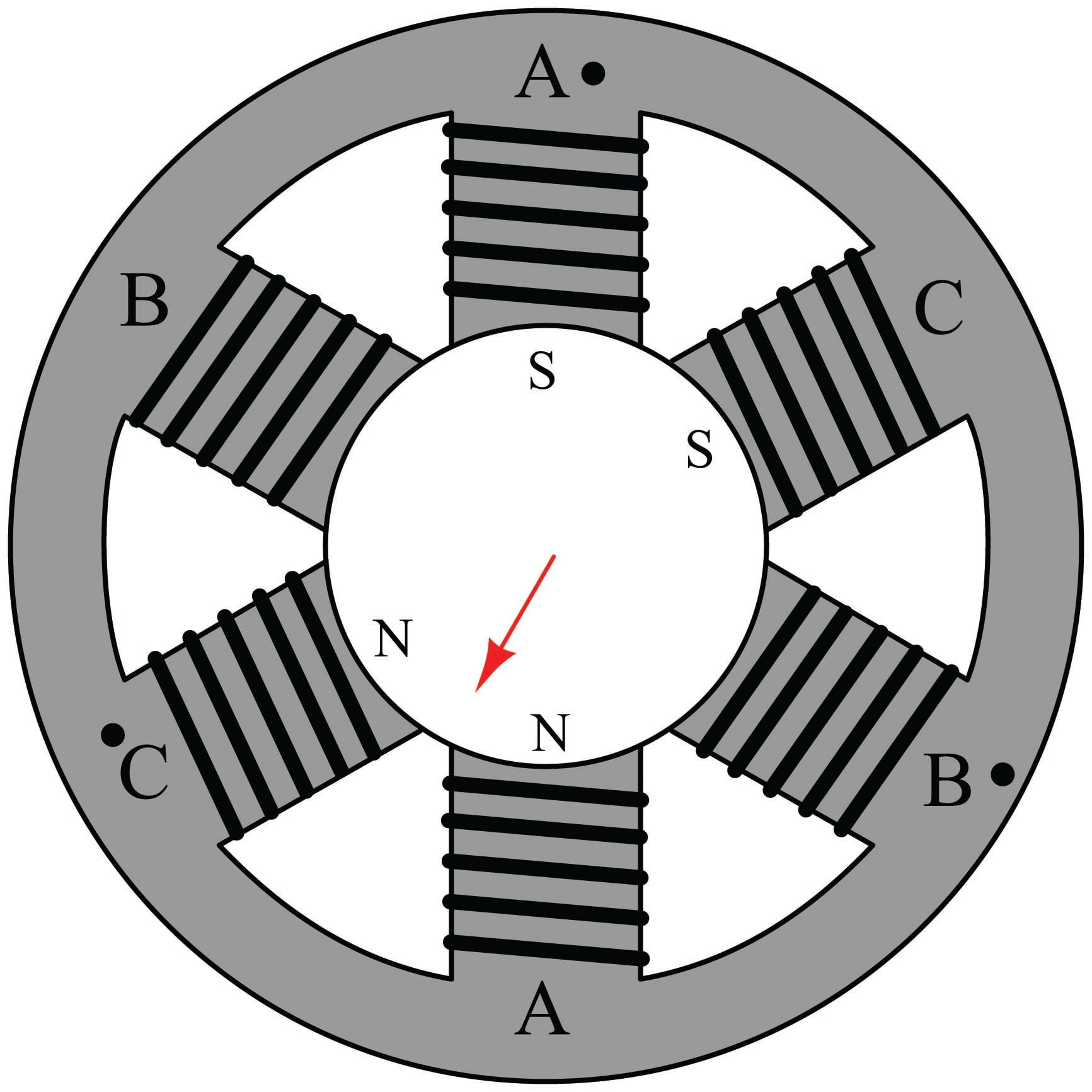
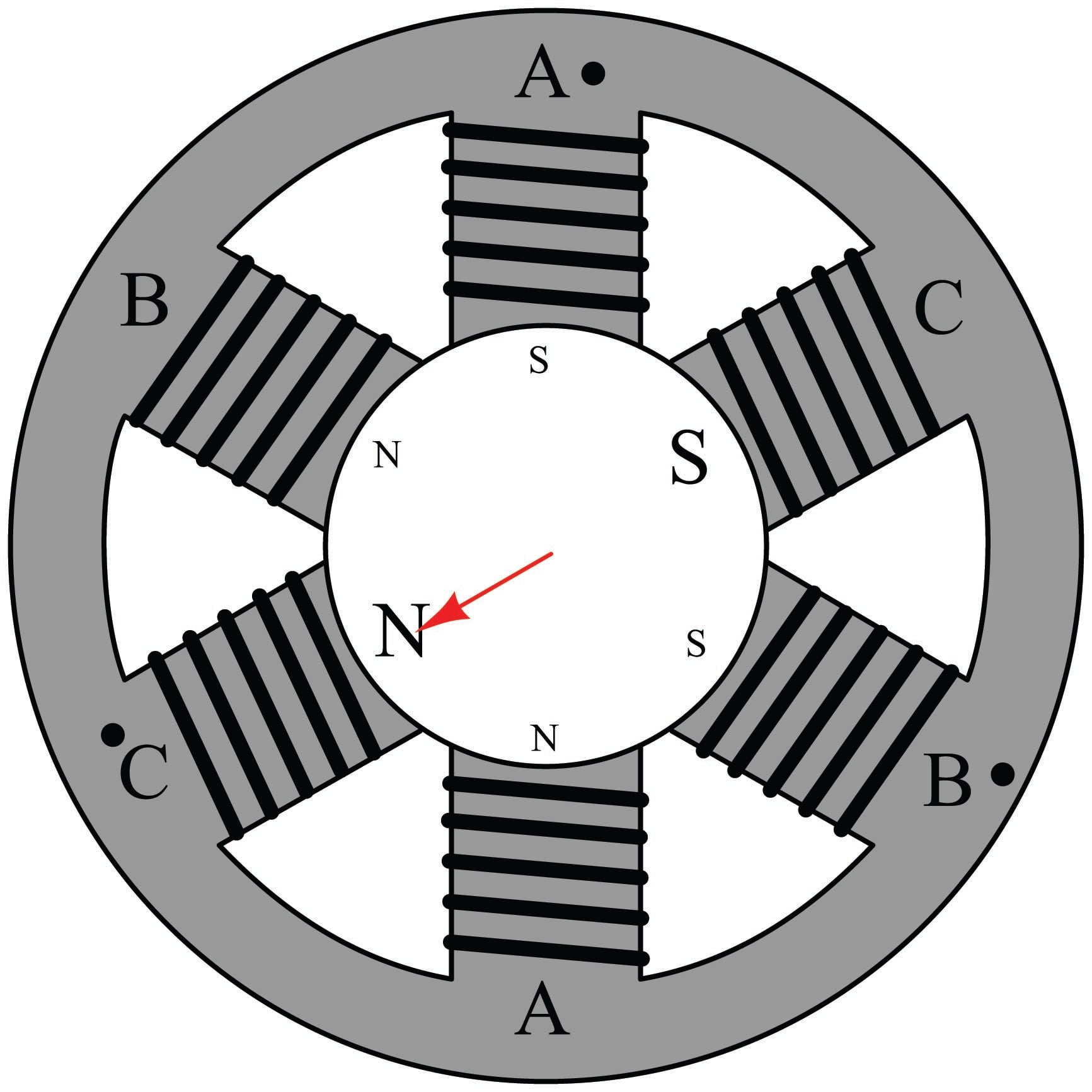
It should come as no surprise that the combined effect of these three-phase currents will be to create a resultant magnetic field vector rotating in a particular direction. After all, this is precisely how three-phase electric power is generated: by spinning a single magnet at the center of three sets of coils offset by 120 degrees. The rotating magnetic field generated by the stator windings of a three-phase motor is merely a reproduction of the rotor’s magnetic field inside the generator supplying the three-phase power!
If a permanent magnet were placed within the center of this machine on a shaft such that it was free to rotate, the magnet would spin at the exact same speed as the rotating magnetic field. If the magnetic field completes one full revolution in \({1 \over 60}\) of a second, the rotating speed of the magnet will be 60 revolutions per second, or 3600 revolutions per minute (3600 RPM). Since the magnet follows in lock-step with the rotating magnetic field, its rotational speed is said to be synchronous. We would thus identify this motor as a synchronous AC motor.
If an electrically conductive object were placed within the center of this same machine on a shaft such that it was free to rotate, the relative motion between the rotating magnetic field and the conductive object (rotor) would induce electric currents in the conductive object, producing magnetic fields of their own. Lenz’s Law tells us that the effect of these induced magnetic fields would be to try to oppose change: in other words, the induced fields react against the rotating magnetic field of the stator coils in such a way as to minimize the relative motion. This means the conductive object would begin to rotate in the same direction as the stator’s rotating magnetic field, always trying to “catch up” to the rotating magnetic field. However, the conductive rotor could never exactly match the speed of the rotating magnetic field as in the case of a synchronous motor. If the rotor ever did achieve synchronous speed, there would no longer be any relative motion between the rotor and the rotating magnetic field, which means the induction would cease. No induction would mean no electric currents induced in the rotor, which would mean no reactive magnetic field, which would mean no torque to motivate the rotor. Thus, the electrically conductive rotor’s speed must always slightly lag (“slip”) behind the rotating magnetic field’s synchronous speed in order to experience induction and thereby be able to create torque. We call this type of motor an induction AC motor.
It may come as a surprise for some to learn that any conductive object – ferromagnetic or not – will experience a torque when placed inside the rotating magnetic field generated by the stator coils. So long as the object is electrically conductive, electromagnetic induction will ensure the creation of electric currents in the rotor, and these currents will produce their own magnetic fields that react against the stator’s rotating magnetic field to produce a torque on the rotor.
The effect of Lenz’s Law between a magnet and a conductive object may be demonstrated by using a powerful permanent magnet and a strip of light-weight aluminum foil. Aluminum, of course, is electrically conductive but non-magnetic. However, despite the lack of magnetic attraction between the magnet and the foil, the foil will nevertheless experience a motive force if the magnet is swept past its surface rapidly, due to Lenz’s Law:

This very same principle is what makes an induction AC motor function: a rotating magnetic field induces electric currents in an electrically-conductive rotor, which then spins in the same direction as the magnetic field. An induction motor’s rotor can never achieve synchronous speed on its own, for if it ever did the induction would cease due to a lack of relative motion between the rotating magnetic field and the rotor. The same is true of the aluminum foil strip experiments: the foil strip can never fully “catch up” to the moving magnet, for if it ever did the induction would cease and the motive force would disappear. Thus, induction machines always spin a bit slower than synchronous speed.
A typical “two-pole” induction motor operating at a power line frequency of 60 Hz has a synchronous speed of 3600 RPM (i.e. the rotating magnetic field is spinning 60 revolutions per second), but the rotor may only achieve a full-load speed of approximately 3540 RPM. Similarly, a typical “four-pole” induction motor with a synchronous speed of 1800 RPM may only attain a rotor speed of approximately 1760 RPM.
Induction motors are by far the most popular design in industry. The most common variant of the induction motor is the so-called squirrel-cage design, where the rotor is made up of aluminum bars joining two aluminum “shorting rings,” one at either end of the rotor. Ferrous metal (iron alloy) fills the spaces between the rotor bars to provide a lower-reluctance magnetic “circuit” between stator poles than would otherwise be a large air gap if the rotor were simply made of aluminum. If the ferrous metal were removed from the rotor, the remaining aluminum bars and shorting rings would resemble the cage-wheel exercise machine used by hamsters and other pet rodents, hence the name.
A photograph of a small, disassembled three-phase AC induction “squirrel-cage” motor is shown here, revealing the construction of the stator coils and the rotor:

Given the extremely simple construction of AC induction motors, they tend to be very reliable. So long as the stator coil insulation is not damaged by excessive moisture, heat, or chemical exposure, these motors will continue to operate indefinitely. The only “wearing” components are the bearings supporting the rotor shaft, and those are easily replaced.
Starting a three-phase induction motor is as simple as applying full power to the stator windings. The stator coils will instantly produce a magnetic field rotating at a speed determined by the frequency of the applied AC power, and the rotor will experience a large torque as this high-speed (relative to the rotor’s stand-still speed of zero) magnetic field induces large electric currents in it. As the rotor comes up to speed, the relative speed between the rotating magnetic field and the rotating rotor diminishes, weakening the induced currents and also the rotor’s torque.
One way to “model” an AC induction motor is to think of it as an AC transformer with a short-circuited, movable secondary winding. When full power is first applied, the initial current drawn by the stator (primary) windings will be very large, because it “sees” a short-circuit in the rotor (secondary) winding. As the rotor begins to turn, however, this short-circuit draws less and less current until the motor reaches full speed and the line current approaches normal. As with a transformer, where a reduction in secondary current (from a load change) results in a reduction in primary current, the reduction in induced rotor current (from reduced slip speed) results in a reduction in stator winding current.
The huge surge of current at start-up time (as much as ten times the normal running current!) is called inrush current, causing the rotor to produce a large mechanical torque. As the rotor gains speed, the current reduces to a normal level, with the speed approaching the “synchronous” speed of the rotating magnetic field. If somehow the rotor achieves synchronous speed (i.e. the slip speed becomes zero), the stator current will fall to an absolute minimum. If a mechanical power source “over-drives” a powered induction motor, forcing it to spin faster than synchronous speed, it will actually begin to function as a generator and sourced electrical power.
Any mechanical load causing the motor to spin slower likewise causes the stator windings to draw more current from the power supply. This is due to the greater slip speed causing stronger currents to be induced in the rotor. Stronger rotor currents equate to stronger stator currents, just like a transformer where a heavier load on the secondary winding causes greater currents in both secondary and primary windings.
Reversing the rotational direction of a three-phase motor is as simple as swapping any two out of three power conductor connections. This has the effect of reversing the phase sequence of the power “seen” by the motor. The flip-book animation beginning in Appendix [animation_blinking_lights] beginning on the page shows how reversing two of the three lines has the effect of reversing phase sequence.
An interesting problem to consider is whether it is possible to make an AC induction motor function on single-phase power rather than polyphase power. After all, it is the three-step phase sequence of three-phase AC power that gives the stator windings’ magnetic field its definite rotational direction. If we have only one sine wave supplied by the AC power source, is it possible to generate a truly rotating magnetic field? At best, it seems all we could ever produce with single-phase AC power is a pulsing or “blinking” magnetic field. If you imagine a string of light bulbs blinking on and off 180\(^{o}\) out of phase (i.e. ABABABAB), one could argue the sequence is marching from A to B, or alternatively from B to A – there is no definite direction to the lights’ “motion.”
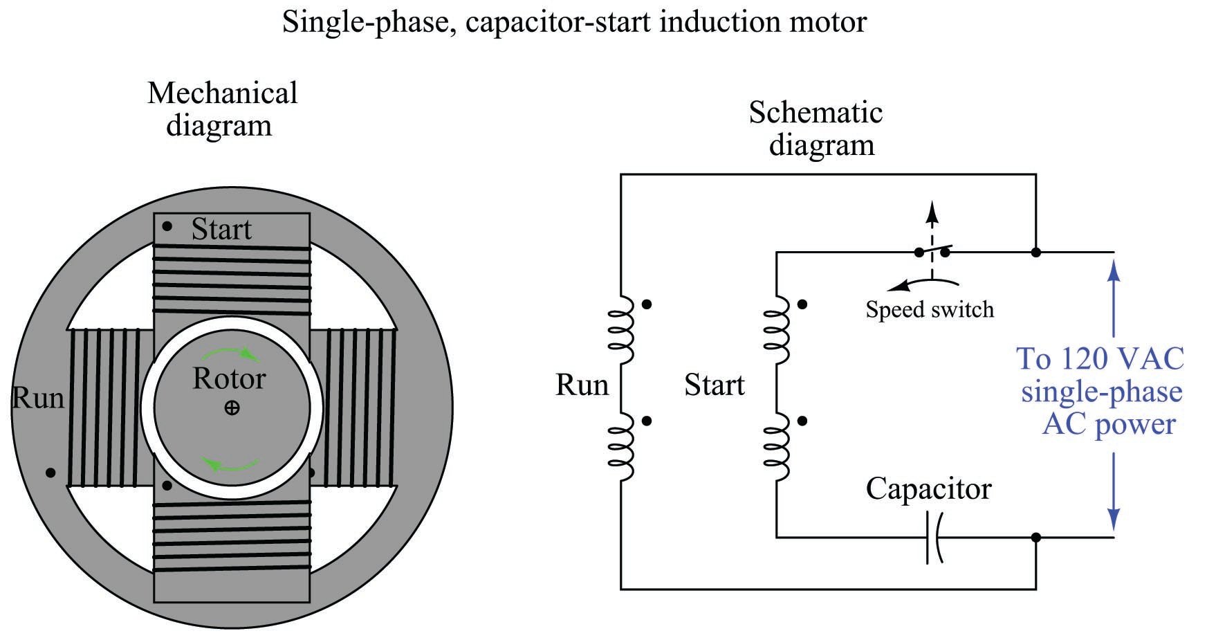
Since single-phase AC induction motors obviously exist, there must be a solution to this problem. In order to give the magnetic field within a single-phase stator assembly a definite rotation, we must artificially create a second phase within the motor itself. One common way to do this is to add a second set of stator windings offset from the first and energize those windings through a high-voltage capacitor, which creates a leading phase shift in winding current. This phase shift creates an out-of-step magnetic field in the second winding set, providing a definite direction of rotation. Once the motor comes up to speed, this auxiliary winding may be disconnected by a speed-sending switch, since a spinning motor will happily run on single-phase AC. This is called a capacitor-start induction motor, and it is the design used for most single-phase AC induction motors requiring a high starting torque (e.g. pumps, shop grinders, drill presses, etc.):
One of the major principles to grasp about AC induction motors is that they must start as polyphase machines, although they may continue to run as single-phase machines.
A capacitor-start, single-phase electric motor is shown in the following photograph. My hand is touching the capacitor enclosure for the motor’s starting winding. The speed switch is internal to the motor and cannot be seen in this photograph:

Capacitor-start motors are often designed in such a way that the starting winding draws much more current than the “run” winding, in order to provide a strong starting torque. This is important when the mechanical load being turned by the motor requires a great deal of torque to get moving, such as in the case of a reciprocating gas compressor or a fully-loaded conveyor belt. Due to this high current draw, starting windings are not rated for continuous duty, but rather must be de-energized shortly after starting the motor in order to avoid overheating.
Smaller AC motors, such as those used inside bench-top and rack-mount electronic equipment, use a completely different method for generating a rotating magnetic field from single-phase AC power. The following photograph shows one such motor, employing copper shading coils at the corners of the magnetic stator poles. The rotor has been removed, held by my fingers for inspection:
[shading_coil]

Instead of a capacitor creating a leading phase-shift for current through a special stator winding, this “shaded-pole” induction motor uses a pair of copper loops wrapped around the corners of the magnetic poles to produce a lagging phase shift in the magnetic field at those corners. The copper shading coils act as inductors, delaying the magnetic field through them by \(-90^{o}\), creating a secondary magnetic field that is out-of-step with the main magnetic field generated by the rest of the pole face. The out-of-step magnetic field together with the main magnetic field adjacent to it creates a definite direction of rotation.
An interesting experiment you can try yourself is to obtain one of these small shaded-pole AC motors and make it rotate by applying pulsed DC power to it, from a battery. Every time you connect the stator winding to the battery, the increasing magnetic flux will lead at the non-shaded pole faces and lag at the shaded pole faces. Every time you disconnect the stator winding from the battery, the decreasing magnetic flux will lead at the non-shaded pole faces and lag at the shaded pole faces. In either case, the shaded poles’ magnetic flux will lag behind that of the non-shaded poles, causing the rotor to rotate slightly in one definite direction.
The fact that all AC induction motors must start as polyphase machines even though they can run as single-phase machines means that an AC motor designed to run on three-phase power may actually continue to run if one or more of its phases are “lost” due to an open wire connection or a blown fuse. The motor cannot deliver full-rated mechanical power in this condition, but if the mechanical load is light enough the motor will continue to spin even though it no longer has multiple phases powering it! A three-phase motor, however, cannot start from a stand-still on just one phase of AC power. The loss of phases to an AC induction motor is called single-phasing, and it may cause a great deal of trouble in an industrial facility. Three-phase electric motors that become “single-phased” from a fault in one of the three-phase power lines will refuse to start. Those that were already running under heavy (high-torque) mechanical load will stall. In either case, the stopped motors will simply “hum” and draw large amounts of current.
Motor contactors
To start up and shut down a three-phase AC induction motor, any three-pole switch with a suitable current rating will suffice. Simply closing such a switch to send three-phase power to the motor will cause it to start up while opening the three-pole switch will cut power to the motor to make it turn off. If we desire to have remote start and stop control over a three-phase motor, we need a special relay with switch contacts big enough to safely conduct the motor’s inrush current over many starts and stop cycles. Large, high-current-rated electromechanical relays built for this very purpose are commonly referred to as contractors in the industry.
A schematic diagram of a three-phase contactor connected to a three-phase motor (with fuses for overcurrent protection) is shown here:

Energizing terminals A1 and A2 magnetizes the electromagnet coil, causing all three switch contacts to simultaneously close, sending three-phase AC power to the motor. De-energizing the coil causes it to de-magnetize, releasing the armature and enabling a return spring inside the contactor to snap all three contacts to the open (off) position.
A contactor rated at 75 horsepower (at 480 volt AC 3-phase power) is shown here, both assembled and with the top cover removed to reveal the three sets of high-current electrical switch contacts:


Each phase switch contact is actually a series pair of contacts that make and break simultaneously with the actuation of a ferrous armature attracted by an electromagnet coil in the base of the contactor assembly. The operation of the three contact sets may be seen in this pair of photographs, the left-hand image showing the contacts in their normal (open) state, and the right-hand image showing the contacts closed (the armature “pulled in”) by the force of my finger:


Of course, it would be very dangerous to touch or manually actuate the contacts of a motor starting relay with the cover removed as shown. Not only would there be an electric shock hazard from touching any one of the bare copper contacts with your finger, but the arcing produced by closing and opening such contacts would pose arc flash and arc blast hazards. This is why all modern motor contactors are equipped with arc shield covers. The actual switch contact pads are not made of pure copper, but rather silver (or a silver alloy) designed to survive the repeated arcing and blasting action of large AC currents being initiated and interrupted.
Below the main power connection terminals (L1-L3, T1-T3) on this contactor hide two small screw terminals (commonly denoted A1 and A2) providing connection points to the electromagnet coil actuating the contactor:

Like most three-phase contactors, this one’s coil is rated for 120 volts AC. Although the electric motor may operate on three-phase, 480 volt AC power, the contactor coil and the rest of the control circuitry operate on a lower voltage for reasons of safety. Like all electromechanical relays, motor contactors use a low-power signal to control higher-power electric current to the load. This “amplifying” action enables relatively small control switches, PLCs, and relay circuits to start and stop relatively large (high-current) electric motors.
Motor protection
An essential component of any high-power motor control circuit is some device to detect a condition of excessive overload and interrupt power to the motor before thermal damage occurs. A very simple and common overload protective device is known as an overload heater, consisting of resistive elements connected in series with the three lines of a 3-phase AC motor, designed to heat and to cool at rates modeling the thermal characteristics of the motor itself.
Fuses and circuit breakers also protect against overcurrent, but for different reasons and for different parts of the motor circuit. Both fuses and circuit breakers tend to be fast-acting devices, intended to interrupt overcurrent resulting from an electrical fault such as a phase-to-ground short circuit. They are sized to protect the wiring delivering power to a load, not (necessarily) the load itself. Thermal overload heaters, by contrast, are specifically designed to protect an electric motor from damage resulting from mild overcurrent conditions, such as what might be experienced if the motor becomes mechanically overloaded. The sizing of overload heaters is unrelated to wire ampacity, and therefore unrelated to the ratings of the fuses or circuit breakers delivering line power to the motor.
A schematic diagram of a three-phase overload connected to a three-phase contactor and the three-phase motor is shown here:

Both contacts inside the overload assembly will remain in their resting (“normal”) state so long as the heater elements (the back-to-back “hook” symbols seen in the above diagram) remain cool. If one or more of the resistive heaters becomes too warm, however, the contacts will actuate and change the state. The normally-closed overload contact (terminals 95 and 96) is typically wired in series with the contactor coil (terminals A1 and A2) so that a detected overload condition forces the contactor to de-energize and interrupt power to the motor.
The following photograph shows a three-phase contactor relay joined together with a set of three “overload heaters” through which all of the motor’s current flows. The overload heaters appear as three brass-colored metal strips near a red push-bar labeled “Reset”. The entire assembly – contactor plus overload heaters – is referred to as a starter:

Removing one of the heater elements reveals its mechanical nature: a small toothed wheel on one side engages with a lever when it is bolted into place in the overload assembly. That lever connects to a spring-loaded mechanism charged by the manual actuation of the red “Reset” push-bar, which in turn actuates a small set of electrical switch contacts:

The purpose of the overload heater is to heat up as the motor draws excessive current. The small toothed wheel is held in place by a rod immersed in a solidified mass of solder, encased in a brass cylinder underneath the heater strip. The next photograph shows the underside of the heater element, with the toothed wheel and brass cylinder plainly visible:

If the heater element becomes too hot (due to excessive motor current), the solder inside the brass cylinder will melt, allowing the toothed wheel to spin. This will release spring tension in the overload mechanism, allowing the small electrical switch to spring to an open state. This “overload contact” then interrupts current to the contactor’s electromagnet coil, causing the contactor to de-energize and the motor to stop.
Manually pressing the “Reset” push-bar will re-set the spring mechanism and re-close the overload contact, allowing the contactor to energize once more, but only once the overload heater element has cooled down enough for the solder inside the brass cylinder to re-solidify. Thus, this simple mechanism prevents the overloaded motor from being immediately re-started after a thermal overload “trip” event, giving it time to cool down as well.
A typical “trip curve” for a thermal overload unit is shown here, with time plotted against the severity of the overcurrent level:

In contrast to a circuit breaker or fuse – which is sized to protect the power wiring from overcurrent heating – the overload heater elements are sized specifically to protect the motor. As such, they act as thermal models of the motor itself, heating to the “trip” point just as fast as the motor itself will heat to the point of maximum rated temperature, and taking just as long to cool to a safe temperature as the motor will. Another difference between overload heaters and breakers/fuses is that the heaters are not designed to directly interrupt current by opening, as fuses or breakers do. Rather, each overload heater serves the simple purpose of warming proportionately to the magnitude and time duration of motor overcurrent, causing a different electrical contact to open, which in turn triggers the contactor to open and interrupt motor current.
Of course, overload heaters only work to protect the motor from thermal overload if they experience similar ambient temperature conditions. If the motor is situated in a very hot area of the industrial process unit, whereas the overload elements are located in a climate-controlled “motor control center” (MCC) room, they may fail to protect the motor as designed. Conversely, if the overload heaters are located in a hot room while the motor is located in a freezing-cold environment (e.g. the MCC room lacks air conditioning while the motor is located in a freezer), they may “trip” the motor prematurely.
An interesting “trick” to keep in mind for motor control circuit diagnosis is that overload heaters are nothing more than low-value resistors. As such, they will drop small amounts of voltage (usually quite a bit less than 1 volt AC) under full load current. This voltage drop may be used as a simple, qualitative measure of motor phase current. By measuring the voltage dropped across each overload heater (with the motor running), one may ascertain whether or not all phases are carrying equal currents. Of course, overload heaters are not precise enough in their resistance to serve as true current-measuring “shunts,” but they are more than adequate as qualitative indicators of relative phase current, to aid you in determining (for instance) if the motor suffers from an open or high-resistance phase winding:

As useful as thermal overload “heaters” is for motor protection, there are more effective technologies available. An alternative way to detect overloading conditions is to monitor the temperature of the stator windings directly, using thermocouples or (more commonly) RTDs, which report winding temperatures to an electronic “trip” unit with the same control responsibilities as an overload heater assembly. This sophisticated approach is used on large (thousands of horsepower) electric motors, and/or in critical process applications where motor reliability is paramount. Machine vibration equipment used to monitor and protect against excessive vibration in rotary machines is often equipped with such temperature-sensing “trip” modules just for this purpose. Not only can motor winding temperatures be monitored, but also bearing temperatures and other temperature-sensitive machine components so that the protective function extends beyond the health of the electric motor.
Devices specifically constructed to monitor the condition of electrical power components such as motors, generators, transformers, or distribution lines, and take action to protect those components in the event their parameters fall outside safe limits, are generally known as protective relays. A protective relay is designed to monitor physical variables such as line currents and winding temperatures relevant to a large electrical component, then automatically initiate a “trip” action to shut off power to that component by sending a signal to the nearest circuit breaker or other automatic disconnect devices.
Originally, protective relays were electromechanical in nature, using coils, magnets, springs, rotating disks, and other components to detect and act upon out-of-spec electrical measurements. Modern protective relays – for electric motors or for other electric power components such as generators, power lines, and transformers – use microprocessors instead of electromagnetic mechanisms to perform the same basic functions. With microprocessor technology comes vast increases in responsiveness and precision of timing, as well as digital networking capability to share system data among other components and to human operators.
A diagram showing how a modern (digital) protective relay would monitor various parameters on a medium-voltage (4160 volts AC, three-phase) industrial electric motor is shown here:
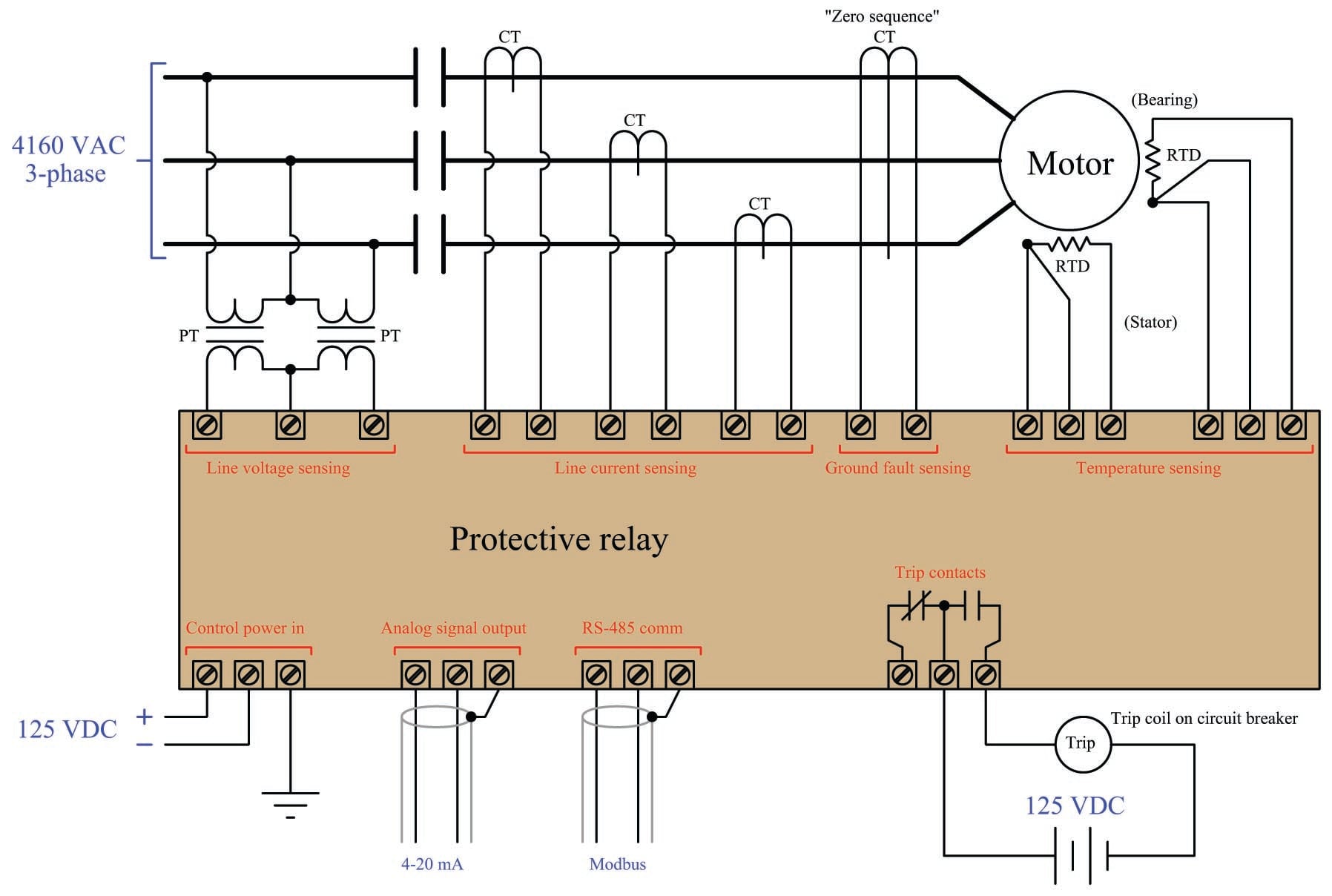
In this example, line voltage (4160 volts AC) and line current are both too great to be directly connected to the protective relay, and so the relay senses line voltage and line current via potential transformers (PTs) and current transformers (CTs), respectively. A potential transformer is a precision device providing a known accurate step-down ratio, usually down to 120 volts or 240 volts AC full-scale, for the protective relay to directly sense. Likewise, a current transformer is a precision device providing a known and accurate step-down ratio for current (actually a step-up from the perspective of voltage), usually down to 1 amp or 5 amps AC full-scale, for the protective relay to directly sense. Both transformers provide galvanic isolation (a complete lack of electrical conductivity) between the medium-voltage motor power conductors and the protective relay electronics while still permitting accurate sensing of line voltage and line current.
The zero-sequence CT is a special current transformer encircling all three motor phase conductors, providing an indication of a ground fault within the motor. The fact that this CT measures the instantaneous algebraic sum of currents in and out of the motor means that in ordinary operation it will output absolutely zero signal, since Kirchhoff’s Current Law states that the algebraic sum of currents into and out of a node (the motor here is considered a node) must be zero. If, however, a ground fault develops within the motor where some AC current “leaks” from a stator winding to earth ground to return to the 4160 VAC power source’s neutral connection, that imbalance of phase currents will be sensed by the zero-sequence CT, since that ground-fault current represents the fourth path for current not accounted for by the three power conductors passing through to the motor.
This next photograph shows the front panel display of a General Electric (“Multilin”) model 369 protective relay for an electric motor:

Motor control circuit wiring
A simple three-phase, 480 volt AC motor-control circuit is shown here, both in pictorial and schematic form. This entire assembly consisting of contactor, overload block, control power transformer, power fuses (or alternatively, a circuit breaker) and associated components is informally referred to as a bucket:
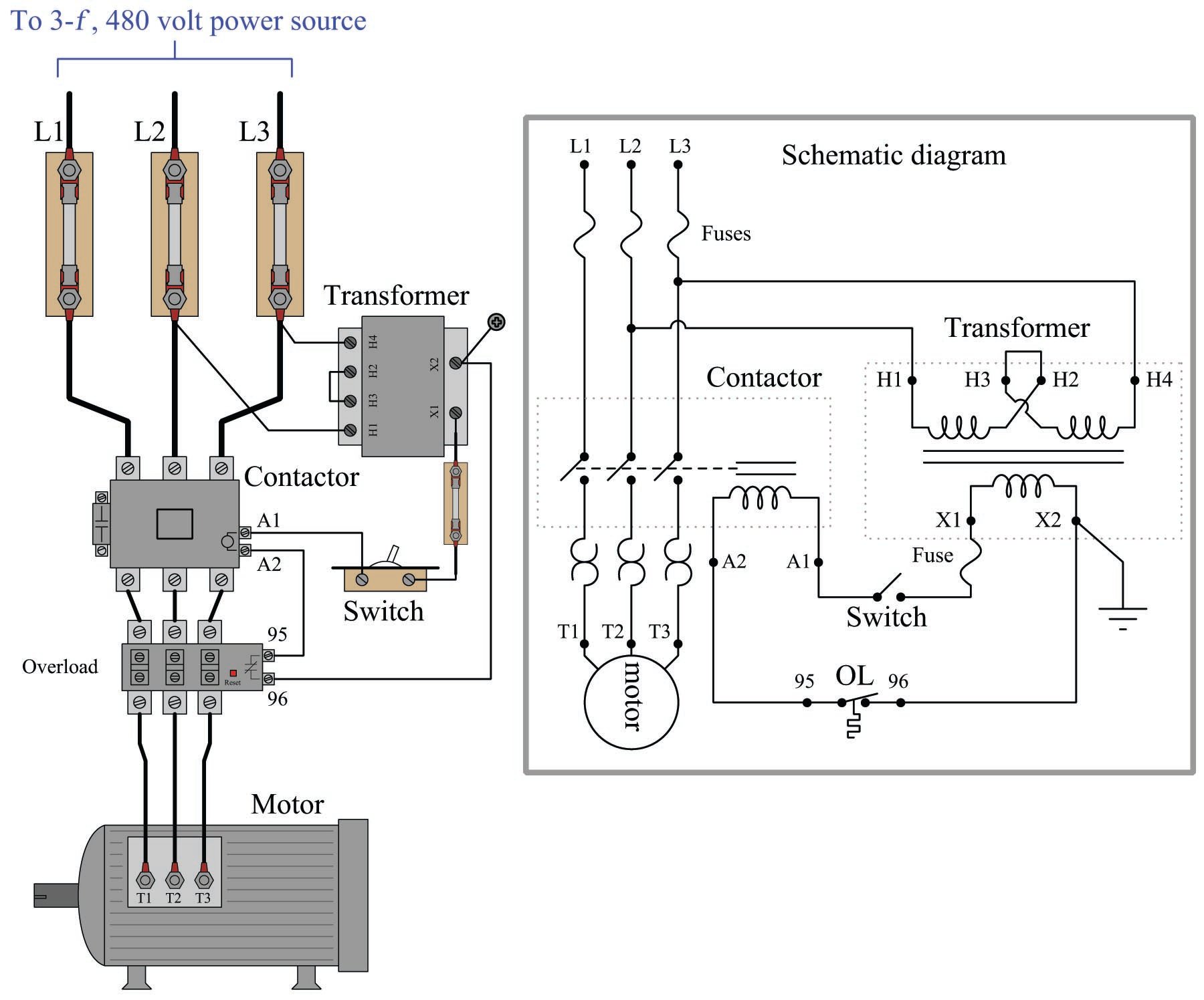
Note how a control power transformer steps down the 480 volt AC to provide 120 volt AC power for the contactor coil to operate on. Furthermore, note how the overload (“OL”) contact is wired in series with the contactor coil so that a thermal overload event forces the contactor to de-energize and thus interrupt power to the motor even if the control switch is still in the “on” position. The overload heaters appear in the schematic diagram as pairs of back-to-back “hook” shapes, connected in series with the three “T” lines of the motor. Remember that these “OL” heater elements do not directly interrupt power to the motor in the event of an overload, but rather signal the “OL” contact to open up and de-energize the contactor.
In an automatic control system, the toggle switch would be replaced by another relay contact (that relay controlled by the status of a process), a process switch, or perhaps the discrete output channel of a programmable logic controller (PLC).
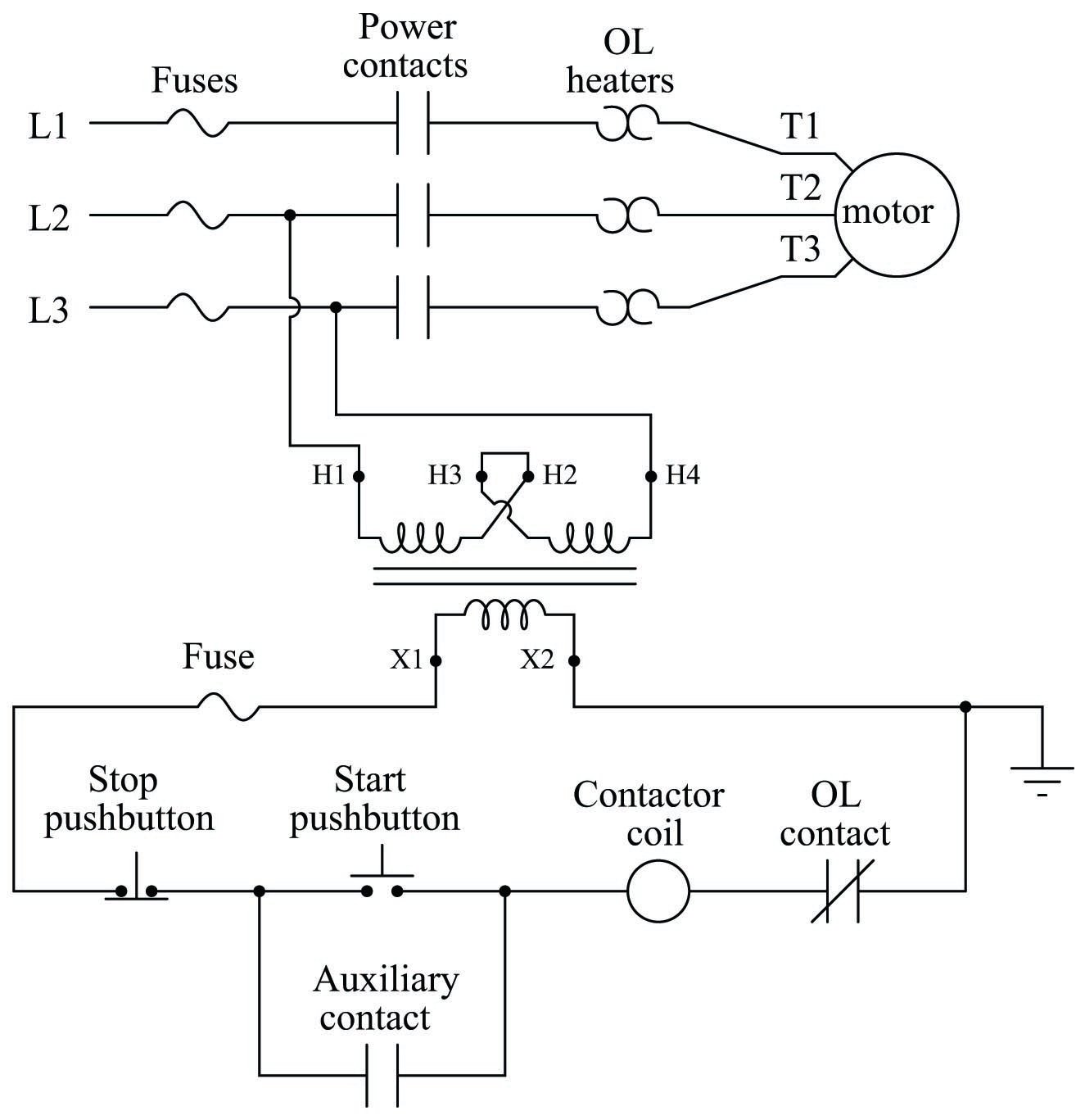
It should be noted that a toggling-style of switch is necessary in order for the motor to continue to run after a human operator actuates the switch. The motor runs when the switch is in the closed state, and stops when the switch opens. An alternative to this design is to build a latching circuit allowing the use of momentary contact switches (one to start, and one to stop). A simple latching motor control circuit is shown here:

In this circuit, an auxiliary contact actuated by the motor contactor is wired in parallel with the “Start” pushbutton switch, so that the motor contactor continues to receive power after the operator releases the switch. This parallel contact – sometimes called a seal-in contact – latches the motor in an “on” state after a momentary closure of the “Start” pushbutton switch.
A normally-closed “Stop” switch provides a means to “un-latch” the motor circuit. Pressing this pushbutton switch opens the control circuit, forcing current to halt through the coil of the contactor, which then opens the three motor power contacts as well as the auxiliary contact used to maintain the contactor’s energized state.
A simple ladder diagram showing the interconnections of all components in this motor control circuit makes this system easier to understand:
Most on/off motor control circuits in the United States are some variation on this wiring theme, if not identical to it. Once again, this system could be automated by replacing the “Start” and “Stop” pushbutton switches with process switches (e.g. pressure switches for an air compressor control system) to make a system that starts and stops automatically. A programmable logic controller (PLC) may also be used to provide the latching function rather than an auxiliary contact on the contactor. Once a PLC is included in the motor control circuit, a great many automatic control features may be added to enhance the system’s capabilities. Examples include timing functions, motor cycle count functions, and even remote start/stop capability via a digital network connecting to operator interface displays or other computers.
In applications where reversing motor control is desired, a pair of contactors may be wired together as shown here:
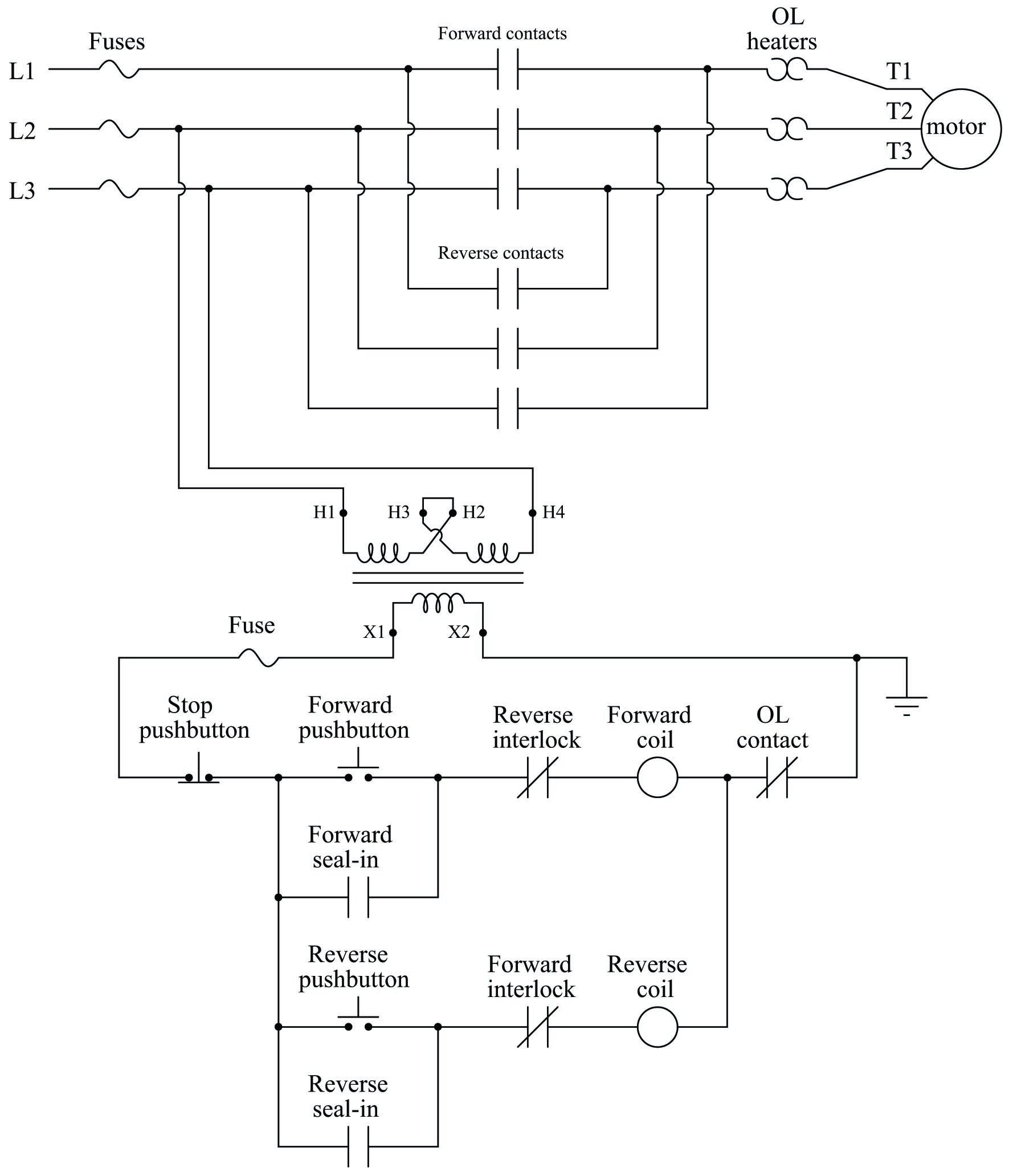
Note how motor reversal is accomplished by swapping phases L1 and L3: in the forward direction, power line conductor L1 connects to motor terminal T1, L2 connects to T2, and L3 connects to T3. In the reverse direction L2 still connects to T2, but L1 now connects to T3 and L3 now connects to T1. Recall the principle that swapping any two phases in a three-phase power system reverses the phase rotation, which in this case make the electric motor spin the other direction.
With two contactors, the control circuit now contains two coils to actuate those contactors: one marked “forward” and the other marked “reverse”. Separate “forward” and “reverse” pushbutton switches send power to those coils, and separate seal-in auxiliary contacts connected in parallel with their respective pushbuttons latch each one.
An important feature of this reversing starter circuit is the inclusion of interlocking contacts in each rung of the circuit. In the forward-control circuit, a normally-closed auxiliary contact actuated by the “reverse” contactor is wired in series, and vice-versa in the reverse-control circuit. The purpose of an “interlock” is to prevent incompatible events from happening, in this case preventing the actuation of the “reverse” contactor when the “forward” contactor is already actuated, and vice-versa. If both contactors were to be simultaneously actuated, it would result in a direct phase-to-phase fault (short-circuit) between L1 and L3!
Some reversing motor starters provide a feature called mechanical interlocking, where the motion of the armature in each contactor is restrained in such a way that both cannot actuate simultaneously. This usually takes the form of a “rocking beam” lever preventing one contactor armature from being pulled in while the other contactor’s armature is pulled in, similar to a “see-saw” playground toy where only one end can be down at any given time. It is not uncommon for both electrical and mechanical interlocking to be used in the same reversing starter, as a measure of extra protection.
A modern trend in motor control is the use of digital networks to both command the contactor as well as monitor the motor’s operating status remotely. This next photograph shows a digitally monitored and controlled “bucket,” using DeviceNet as the control network:

Using a digital network standard such as Ethernet, DeviceNet, Modbus, Profibus, or any number of others to monitor and control a motor brings a host of benefits for maintenance and operations. Control wiring is vastly simplified with digital networks, as a single network cable is able to address multiple motor buckets. The “smart” network interface module installed in the bucket may be designed to monitor such parameters as line voltage, line current, phase imbalance, and power factor to report these values to the host control system via the network.
It is common for the network interface module inside the bucket to have its own digital display for local indication of these parameters as well. A close-up photograph of a Square-D “Motor Logic Plus” unit shows some of its locally-accessible features:

The PLC connected to the network is able to access all these values as well, reporting them to operations and/or maintenance personnel as desired. Instead of individual wires running between the PLC and the motor starter to command each motor to run and stop, the PLC simply transmits “start” and “stop” commands over the network to individually addressed digital starter modules. The network wiring may simply be paralleled (“daisy-chained”) between units, such that several buckets reside on the same physical network, each one programmed with a unique address. A PLC connected to this same network is thus able to access and control all parameters for all motors on that network.

Im working in a hydro power plant and am interested in these motor circuit diagrams. How do i download them please if you can assist. Patrick Yogaro