Applying Hart communication across 2088 pressure transmitter using DS8500 hart modem

hello !
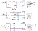
i am trying to setup a hart communication across 2088 pressure transmitter using DS8500 modem which is controlled by arduino uno.
i have connected my transmitter using two wire diagram +24Vdc to + terminal of transmitter and - terminal of voltage source to - terminal of the transmitter. i have 260Ohm resistor inserted in the positive side of the transmitter.
24Vdc+ ------------- 260OHm ------------+ pressure transmitter.

and connected my modem in this order. Fsk_Out of modem on + terminal and Fsk_ on - wire coming out transmitter. yet i am generating code from the AI. and getting no response on my serial monitor. i am not using the digiPin 0 and DigiPin 1 on the arduino uno instead of this i am using DigiPin 2 and DigiPin 3. i have used the logic level shifter Hv=5v and Lv=3.30v and Lv is side is connected to DS8500.

Can anyone verify am i setting this thing correctly ? why my Rx and Tx testing code is not working and why am i not getting response from the transmitter.
 
Yes, i have already checked it but I am stuck at " what should be my circuit with 2088 pressure transmitter (4mA - 20mA+ hart)" what will be the wiring diagram ?

attached below. Are these connections are good ? if they are good why am I not able to generate and receive any signal ?View attachment 4967
This should work.
How do you "generate" a signal?
A properly framed message (with preamble, delimiter, address, command, etc.) must be transmitted or there will be no response from the 2800.
 
Your connections diagrams are confusing because they show 4 terminals, not three.

You mention a 2088 transmitter, presumably a Rosemoount 2088. Presumably yours is not the 3-2ire low power model, and your is the standard loop powered 4-20mA HART model.

The HART 4-20mA 2-wire loop powered connections are shown in the current Rosemount 2088 manual:

https://www.emerson.com/documents/a...s-hart-1-5vdc-low-power-protocol-en-76794.pdf

The manual shows the 2088 has three terminals, not four.

Rosemount 2088 4-20mA HART wiring.JPG

The Rosemount illustration is, unfortunately, not very clear and it is hard to read the labelling under the three terminals, so I have labeled the three terminals D, E and F

Rosemount 2088 4-20mA HART wiring terminals edit DEF.jpg


D is the (+) terminal for conventional 4-20mA field wiring
E is the (-) terminal for conventional 4-20mA field wiring

F is the TEST terminal (when used with E). The TEST terminals are to be used to read the loop current ONLY with a digital mulitmeter on the current range where the multimeter has in internal diode. TEST terminals are not intended for HART communications. Do not connect to F.

Do not connect the GROUND terminal to your HART monitoring circuit.

Do not use your 3-wire proposed connections.

If your transmitter has 4 terminals, you need to figure out which are operational terminals and which are TEST terminals from the documentation of the transmitter.

Connections for a 4-20mA, 2-wire loop powered, Rosemount 2088 (like the Automation Forum.com graphic):

The 24V(+) connects to the 250 Ohm resistor
The 250 resistor connects to the transmitter D terminal
The transmitter E terminal connects to the DDC power supply (-) terminal.

The HART connections are not polarized.
One HART connection lead connects to D
The other HART connection lead connects to E
 
hello,
i have attached my DS8500 to loop current. Below, I will show you the circuit diagram.
1753164428980.jpeg

This is my connection, and I am controlling it using STM32H723ZG. Attached below is the 11-byte signal I am sending to the current loop.
1753164622239.jpeg

i am not able to get any signal back from the sensor. attached below is photos of my transmitter.

1753164705890.jpeg

attached below the connections for the sensor.
1753164828894.jpeg

Now, following are my connections
1. why am i not getting any signal back from my transmitter although it supports hart communication.
2.is there any article or any video which tells me how to control it using STM32.
3. Am i connecting the DS8500 into the loop correctly ?

Please let me know your thoughts.
 
Is the blue trace the voltage across the resistor?
If so, why is there activity following your transmit?
Usually, device's default address is 0, you should transmit:
FF FF FF FF FF 02 80 00 00 82
to poll a device at address 0.
 
Top