How to make The setting high enough to ensure that the relay does not operate for external faults in the presence of ct errors or other measuring errors
And How The relay differential setting shall be based on the maximum error of current transformers for normal operating conditions
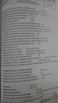
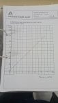
Adjustment of the differential setting ID> is carried out simultaneously on all three phases using the switch K (coarse adjustment) and the switches Z according to the torrnula:
ID> = K(2 + Z) %In
The passible setting values are as follows :
K - 1 : ID> = 2 - 4 - 5 or 7% ot In
K = 2 : ID> = 4 - 8 - 10 or 149a of In
- AdjustmeM of the bias setting is carried out simultaneously on all three phases to the value 9'Ven by the switch KR% (2 - 5 - 10 or 20% bias).
Set the values as defined in the corresponding network protection study. In the absence of any particular constraints, and with absolutely identical line CTs a both ends, a reasonable level of protection is obtained by setting the differential setting to 10% and the bias percentage to 10%.
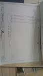
both main breakers of the generators trip simultaneously after energizing transformers TR1 or TR2 with a closed bus tie between them due to relay settings
And How The relay differential setting shall be based on the maximum error of current transformers for normal operating conditions
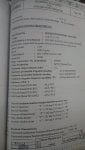
Adjustment of the differential setting ID> is carried out simultaneously on all three phases using the switch K (coarse adjustment) and the switches Z according to the torrnula:
ID> = K(2 + Z) %In
The passible setting values are as follows :
K - 1 : ID> = 2 - 4 - 5 or 7% ot In
K = 2 : ID> = 4 - 8 - 10 or 149a of In
- AdjustmeM of the bias setting is carried out simultaneously on all three phases to the value 9'Ven by the switch KR% (2 - 5 - 10 or 20% bias).
Set the values as defined in the corresponding network protection study. In the absence of any particular constraints, and with absolutely identical line CTs a both ends, a reasonable level of protection is obtained by setting the differential setting to 10% and the bias percentage to 10%.
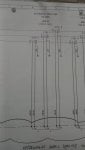
both main breakers of the generators trip simultaneously after energizing transformers TR1 or TR2 with a closed bus tie between them due to relay settings