Finding Proportional Band in PID controller after tuning

we are trying to develop Autotune PID for temperature controller for maintaining temperature in Ovens & write autotune code in C languae.

1. We bought Delta Electronics PID controller DTI4848 & tried to check how they are doing auto tuning.

2. We can measure what temperature by placing our temperature sensor close to Delta temperature sensor. We observed below graph.

a) Blue line is temperature axis multiplied by 100. i.,e 8000 represent 80.0C
b) Red line is for output relay
c) Green arrowed line represent the Tu period for one complete cycle.
d) Yellow marks the max and min limits in time period Tu.

3. Its Åström–Hägglund method or saturation on/off relkay autuning process.

4. But in our case its different, temperature rises above setpoint much higher thean fall below it.
In this case how to find the amplitude? Can you please suggest?
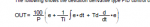
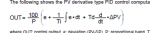
Ku= (4*d)/(pi*y)
where d: is amiplude of Relay output, here we take value 100. Since we will take 100% duty cycle.


5. How to find Proportional band in this?


1589716511618.png
 
I was reading this: https://control.com/forums/threads/pid-proportional-band-limits.29019/

this explains meaning of Pb, but I want to know how to calculate Pb values from graph?
Hi all,

Vindhyachal,

I was reading some documents in the web , on PID autotuning, it looks like There many documents related to this subject.

We know that sometimes it is difficult , to get some kind informations.
Myself i tried to get somed documents , without any reply on this forum.

Saying that, i strongly suggest you to have a read, on the following document , i found it contains very interesting informations also answer to your asked questions.

There is cases examples like the Åström–Hägglund method and how to calculate parameters .

You can also have a check on this graph for better understanding :

https://www.researchgate.net/post/D...n_of_PID_controller_together_with_compensator

I am sure that it can be an help for you!


Do not hesitate to tell us what you find there!

ps: document is written in french as it is a swiss university article but no problem you can do it!
Regards,
James
 

Attachments

Hi thanks for reply @ControlsGuy25

I want to understand what is proprotional band in PID context?
We did some PID tuning test from Delta Electronics temperature controller, and after a test, it gives Pb = 40.
It has unit of degree as per manual.

So what does it mean that suppose at any given point, set point is 100C.
So PID formula will only apply during (100 - (40/2)) to (100 + (40/2)) . i.e 80C to 120C.

If measured temperature is current below 80C, then output is 100% on & if above 120C then output is off completey?
Is this it means?
Hi Vindhyachal,

Hoping that you get at least some informations, that you asking from the document i attached here.

We do not know what kind of process , that you are working on??
It looks like It is temperature controls??

Proportionnal band in PID controller is well explained on the following document:

To answer to your question you can calculate :
Proportionnal band =(controller variable% CHANGE/Final control element CHANGE )*100.

Here is anothers videos to watch :


I dont have lot of experience with PID on ON/OFF relay delaying( Åström–Hägglund method ).
And i also interested to see and know how is behaviour/operation of PI or PID,,,? as i have read that this method is using a PI controller.

Your statement, on Output behaviour of the controller /relay ? seems correct , only the "output is off completely " iam not sure about it as this need to be explained :

Is there kind of limitations/thresholds ?? installed on the control systems? Oh ok I just have look on Device manual and yes there are limitations.
Autotuning seems to be a function available on this product.

Thank you to share with us your opinion,
James
 
Hi
Åström–Hägglund or Saturation relay, people call it by different names.

With this method applied, I am able to calculate Ti & Td values correctly, But this Pb I dont know how to calculate, there is no as such formula I found.

Åström–Hägglund says: Ku = 4D/(pi * A)
D: Output control change
A: change in temperature
pi = 3.14


But how to calculate Pb from it, some says its Pb=100/Ku , some says its will be calculated using entire input temperature range of sensor. But dont understand correct formula


Like in our test, we our output changes from 0 to 100% since its on/off
set point is 70C, minium goes to 69 & max goes to 75C.
So Ku =4*(100-0) / (Pi * (75 - 69))
 
Hi thanks for reply @ControlsGuy25

I want to understand what is proprotional band in PID context?
We did some PID tuning test from Delta Electronics temperature controller, and after a test, it gives Pb = 40.
It has unit of degree as per manual.

So what does it mean that suppose at any given point, set point is 100C.
So PID formula will only apply during (100 - (40/2)) to (100 + (40/2)) . i.e 80C to 120C.

If measured temperature is current below 80C, then output is 100% on & if above 120C then output is off completey?
Is this it means?
Hi

Did you try to use these formulas form Ziegler-Nichols Tuning Method:

PID tuning depends on the user's knowledge of the process to be controlled. Kp, Ki, and Kd are determined by the processes' characteristics, which must be understood before tuning can be performed.
There are two things that must be known about the process:
1. How big is the change in Process Value when Control Value is change by a fixed amount?
2. How quickly does Process Value change in response to a change in Control Value?
The change in PV is simply measured. When compared with CV using a simple equation, the OPEN LOOP GAIN (K) of the system is obtained:
Open Loop Gain (K) = PVstep / CVstep
If a step change in CV causes an identical step change in PV, the Open Loop Gain (K) is one (unity). If a step change in CV causes a step change in PV that is less than CV, the Open Loop Gain (K) is less than 1. If a small step change in CV causes a large change in PV, the Open Loop Gain (K) is greater than 1.
Most processes won't see any change in PV for some time after CV changes. This is called Pipeline Delay Time (Tp) or Dead Time. (Not to be confused with DEAD BAND.)
The Time Constant (Tc) of the process is defined as the time between when the PV first starts to change and the time when PV reaches 63.2% of the expected final PV value.
Find K and Tc
Some experimenting must be done in order to obtain the desired values. This is best done by placing the PID Element into the MANUAL mode, make a small change in CV, and then plot the change in PV. For slow processes this can be done manually, but a strip chart recorder might be helpful.
The change in CV is large enough to cause a measurable change in PV but not so large as to completely disrupt the process being controlled.
The plot looks similar to the above graphic, and K, Tc, and Tp are easily measurable.
Tune the Process
9
If K, Tc, and Tp are known we can use the following equations can be used to estimate starting values for Kp, Ki, and Kd in a Proportional / Integral / Derivative (PID) control:
Kp = (1.2 * Tc) / (K * Tp)
Ki = (0.6 * Tc) / (K * Tp * Tp)
Kd = (0.6 * Tc) / K
Tc and Tp are time units. It is important to ensure that both are expressed in identical units (i.e., milliseconds, seconds, hours, or whatever time frame is appropriate to the process). However, for use in the i³ Configurator PID TUNE dialog, these values must be expressed 10mS intervals (e.g.: "100" = 10mS * 100 = 1 second).
If Proportional-only control (Ki and Kd = 0) is desired, use the equation:
Kp = Tc / (K * Tp)
Or for Proportional / Integral control (Kd = 0), use the equations:
Kp = 0.9 * Tc / (K * Tp)
Ki = 0.3 * Kp / T p
These equations are known as the Ziegler-Nichols tuning method, which were developed by John Zeigler and Nathaniel Nichols in the 1940's.
ulas:


I can attach here a document expalined these formulas.Even it not A DELTA ELECTRONICS it contains lot of interesting informations.
I guess that you should use Ziegler-Nichols for getting /calculate the value you need.

Hope this can help.
James
 
Hi We have calculated Pb, Ti & Td values from grpah and they match what Delta Electronics says.
Pb is mentioned in degree not percentage.

We found one formula from here page 221: https://www.instrumart.com/assets/UT55A-52A-manual.pdf . Lets call in eq(1)


1590072780487.png

But page 92 it has mentioned Pb in percentage while delta electronics is in degrees.

1590072835575.png


Now issue i have is:
1. Can I use above formula? Although pdf manual says its in percentage while Delta electronics is in degrees
2. How to calculate Integral windup limits?
3. I want to limit my output from 0 to 100% duty cycle. SO should put limits on eq(1) 0 to 100?
 

Attachments

Hi We have calculated Pb, Ti & Td values from grpah and they match what Delta Electronics says.
Pb is mentioned in degree not percentage.

We found one formula from here page 221: https://www.instrumart.com/assets/UT55A-52A-manual.pdf . Lets call in eq(1)


View attachment 216

But page 92 it has mentioned Pb in percentage while delta electronics is in degrees.

View attachment 217


Now issue i have is:
1. Can I use above formula? Although pdf manual says its in percentage while Delta electronics is in degrees
2. How to calculate Integral windup limits?
3. I want to limit my output from 0 to 100% duty cycle. SO should put limits on eq(1) 0 to 100?
Hi

It looks like you will need to do back calculation for windup Integral calcul limits.
There some documents available on the web describing how to to so.
If you are using MATLAB SIMULINK, then it is suggested to use back calculation method as there 2 options :

here is some quotes from 2 differents documents :


1st document:


3 PID controllers modelling
In order to avoid this effect in the modeling of PID regulators in automated control systems in software complexes, algorithms for protection against integral saturation are laid down.
For example there are two built-in protection algorithms in Matlab Simulink: Back-Calculation (Figure 1) and Clamping (Figure 2).
Simulink is an interactive tool for modeling, simulating and analyzing dynamic systems. It provides the ability to build graphical block diagrams, simulate dynamic systems, investigate the operability of systems and improve designs. Simulink is fully integrated with MATLAB, providing immediate access to a wide range of analysis and design tools. These advantages make Simulink one of the most popular tool for designing control systems.
In the additional settings of the controller, you can set limits on the input signal. And when using this setting, you can configure protection against the integral saturation effect. This effect occurs when the actuator has a saturation limitation on the input. Because of this limitation, it is not possible to reach the set point, which results in a non-zero error value at the regulator input. During operation, the integrator continues to accumulate this error, the signal at its output increases, but does not participate in the regulation process (does not affect the object). As a result, there is a delay in the transient process. In order to avoid this effect, you must set the limit "Limit output" and choose one of the two methods of protection "Anti-windup method".
Algorithm "back-calculation". In this algorithm, the integral saturation effect occurs with the help of additional feedback, for the transmission of signals, the difference between the received control signal and taking into account the saturation at the integrator input is taken into account. Figure 1 shows the scheme of the "back-calculation" algorithm.
Fig. 1. Back-Calculation algorithm.
The back-calculation anti-windup method uses a feedback loop to discharge the PID Controller's internal integrator when the controller hits specified saturation limits and enters nonlinear operation.
Another commonly used anti-windup strategy is based on conditional integration.

2nd document:
https://controlguru.com/integral-reset-windup-jacketing-logic-and-the-velocity-pi-form/


And here is the MATWORKS link :
https://fr.mathworks.com/help/simulink/slref/anti-windup-control-using-a-pid-controller.html

Again , I am confident by searching the right document the on web, that you will find most of the answers of your questions above.

I strongly suggest you, to have a block diagram exaplining anti windup , then i guess that you will need to get some test by adjusting time constant called "tracking time constant"
Some formulas can be used , you can find them on this interesting article on how test and simulate anti windup:
Some simple rule that have been suggested for the tracking time are ~ Tt = square root(TiTd) and Tt = (Ti + Td)/2. Try these rules.
I will add the document on another thread.

Hope this can help,
Controls guy25
 

Attachments

Hi thanks
i am reading this
Edit: reading links suggested by you

Delta Electronics has this parameter also, i think this is used for integral windup , but i dont know what it is

View attachment 218
I just have read a manual on Delta Electronics PID controller DTI4848 and it seems that :
Proportional control offset is as described in
Regulation function mode: Set the control parameters:
PdoF: Offset output when P or PD control function is ON.
(PID control and Ki=0) can you confirm with your manual?
 
>So PID formula will only apply during (100 - (40/2)) to (100 + (40/2)) . i.e 80C to 120C.
If measured temperature is current below 80C, then output is 100% on & if above 120C then output is off completey?
Is this it means?

I did not read all the subsequent posts some of which seem to reference the Delta product in question, but the 3 or 4 single loop temperature controllers that I have run into, use the span of the input as the value of 100% of proportional band, not the setpoint. So a J thermocouple with an (arbitrary) span of 0-1200°F would have a 100% PB of 1200, until the specified PB limit is reached.
 
Top