I want to ask, hopefully someone can help

Do you have an ohm meter (multimeter)?

It's possible the MCB also has a termination resistor enabled or permanently installed. You could confirm this by powering the device off, disconnecting the wires from the A and B terminals, and measuring the resistance between A and B. If it measures near 120 ohms, then it has a termination resistor, so you would also need to disable or remove this.

If possible, it may be better to connect biasing resistors. You don't have to use exactly 680 ohms, you could probably use anything from between approximately 500 ohms to 1k ohms. They should just both be the same.
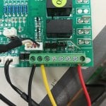
After I removed the resistor on the converter, the result remained the same, checksum error

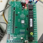
this is my mainboard you can see it
 

Attachments

It's very hard to see, but perhaps R21 is a termination resistor. What numbers are printed on it? If it's 121, and it seems like traces connect it to the terminal block and the S3 jumper posts, then this would strongly indicate it is a termination resistor and S3 enables and disables the resistor between the A and B terminals.
 
It's very hard to see, but perhaps R21 is a termination resistor. What numbers are printed on it? If it's 121, and it seems like traces connect it to the terminal block and the S3 jumper posts, then this would strongly indicate it is a termination resistor and S3 enables and disables the resistor between the A and B terminals.
Do you have any recommendations for a cheap converter that I can use to connect directly to the mainboard?
 

Attachments

Much clearer picture. R110 is definitely a termination resistor (it shows 121 on it). I recommend trying removing the jumper on S3 entirely (it likely connects R110 to the A1 and B1 lines) and move your wires to A1 and B1. Again, remember to try swapping the wires if one polarity doesn't work.

One thing I am confused about is why there are A1/B1 and also A2/B2. Since there are two pairs of A1/B1, I would expect those to be connected together internally and duplicated for the purpose of making daisy-chain wiring easier (only one wire per terminal instead of two). But maybe A2/B2 is a separate RS-485 port? Or maybe it's internally connected to the wallpad connector? Either way, I would try connecting to A1/B1.

As for USB to RS-485 adapters, I would recommend the cables directly from FTDI.
https://ftdichip.com/products/usb-rs485-we-1800-bt/
I've removed the jumper, and tried A1 B1 but the LED on the RXD doesn't light up, the LED only lights up on A2 B2.
My learning about modbus seems to be pretty bad lol
 
I've removed the jumper, and tried A1 B1 but the LED on the RXD doesn't light up, the LED only lights up on A2 B2.
My learning about modbus seems to be pretty bad lol
Ok, that might actually be a good thing. The RXD LED should only flash when the MCB is transmitting a response. Previously, the RXD LED was on all the time, even when the MCB was not sending a response (you saw the same results with reversed polarity and regardless of what device address was being targeted). It's possible that now you only have a mismatch of communication settings (e.g. baud rate, parity, address, etc.).

First thing, though, since you made two changes (moving the wires and removing the jumper), let's confirm that putting the jumper back where it was previously installed results in the behavior you were previously seeing (i.e. RXD LED on and random received bytes in Modbus Poll's Communication Traffic window).

If this is the case, then it would seem to confirm that jumper controls termination and that was one cause of your issue. Note that instead of removing the jumper, alternatively you could move it to the other pins (between positions 1 and 2, instead of between 2 and 3).

If the above is true about the termination on the MCB, then double check your communication settings.
 
Top