Facebook
 Google
 GitHub
 Linkedin
Hello all,
I have been struggling for days to setup Modbus TCP between my Automation Direct HMI (model C5) as the master and a Yaskawa MP3300iec PLC as the slave. I have not found a step-by-step guide to walk me through this (and suspect such a guide specific to my hardware does not exist).
The MP3300iec PLC uses Yaskawa MotionworksIEC (version 3) software.
The HMI uses software "C-MORE" (version 8.22) from Automation Direct.
My immediate goal right now is to communicate ANYTHING between the PLC and the HMI using Modbus TCP. To start with, I am attempting to communicate the value of 1 discreet bit that toggles on/off/on/off. I can not accomplish this.
The Yaskawa MP3300iec (programmed using MotionworksIEC (version 3)) does not have a driver specific to the Automation Direct HMI. Therefore in the Motionworks Hardware Configuration I select "Generic" as the Manufacturer.
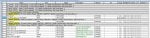
In this same Hardware Configuration screen I set the "Resource" to the name of the Yaskawa PLC ("Ganty_01"). Although currently the only option for "Resource" is the selection called "Retentive" and selecting "Gantry_01" is no longer possible. See attached file. Along the way I did rename the Resource from "Gantry_01" to "MP3300", so that could be part of the reason. Regardless, good or bad, "Retentive" is now the one and only selectable option for "Resource".
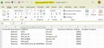
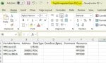
Anyway, when I export the tag list from Motionworksiec, the file format has little in common with the format used by the HMI. So, I edit the exported CSV tag list to a format that the HMI appears to need, and import it to the HMI.
Perhaps the biggest concern is that I added a tag (I added a row to the Global Variables in Motionworks) but this entry is NOT included in the exported tag file. The added tag is "HMI_INPUT...HEARTBEAT" (see image).
I share the images of the CSV files mainly so you can see the headers. I have edited and changed the contents of the CSV files many many times, so I know the images as shared are not correct.
On the HMI side, in the CMORE software, there are options to be selected in the "Protocol Manager" screen. Options I may or may not have selected correctly.
In "Protocol Manager" I have the choice of FC#05 or FC#15 and also a choice of FC#06 or FC#16. I assume CMORE DOES also handle FC#01, 02, 03, 04 as well and they are simple absent from this screen because... no setup is required?
Thank you in advance for any direction you can provide on any aspect of communicating Modbus TCP between these two devices.
I have been struggling for days to setup Modbus TCP between my Automation Direct HMI (model C5) as the master and a Yaskawa MP3300iec PLC as the slave. I have not found a step-by-step guide to walk me through this (and suspect such a guide specific to my hardware does not exist).
The MP3300iec PLC uses Yaskawa MotionworksIEC (version 3) software.
The HMI uses software "C-MORE" (version 8.22) from Automation Direct.
My immediate goal right now is to communicate ANYTHING between the PLC and the HMI using Modbus TCP. To start with, I am attempting to communicate the value of 1 discreet bit that toggles on/off/on/off. I can not accomplish this.
The Yaskawa MP3300iec (programmed using MotionworksIEC (version 3)) does not have a driver specific to the Automation Direct HMI. Therefore in the Motionworks Hardware Configuration I select "Generic" as the Manufacturer.
In this same Hardware Configuration screen I set the "Resource" to the name of the Yaskawa PLC ("Ganty_01"). Although currently the only option for "Resource" is the selection called "Retentive" and selecting "Gantry_01" is no longer possible. See attached file. Along the way I did rename the Resource from "Gantry_01" to "MP3300", so that could be part of the reason. Regardless, good or bad, "Retentive" is now the one and only selectable option for "Resource".
Anyway, when I export the tag list from Motionworksiec, the file format has little in common with the format used by the HMI. So, I edit the exported CSV tag list to a format that the HMI appears to need, and import it to the HMI.
Perhaps the biggest concern is that I added a tag (I added a row to the Global Variables in Motionworks) but this entry is NOT included in the exported tag file. The added tag is "HMI_INPUT...HEARTBEAT" (see image).
I share the images of the CSV files mainly so you can see the headers. I have edited and changed the contents of the CSV files many many times, so I know the images as shared are not correct.
On the HMI side, in the CMORE software, there are options to be selected in the "Protocol Manager" screen. Options I may or may not have selected correctly.
In "Protocol Manager" I have the choice of FC#05 or FC#15 and also a choice of FC#06 or FC#16. I assume CMORE DOES also handle FC#01, 02, 03, 04 as well and they are simple absent from this screen because... no setup is required?
Thank you in advance for any direction you can provide on any aspect of communicating Modbus TCP between these two devices.
Attachments
-
 137.8 KB Views: 5
 -
 94.6 KB Views: 4
 -
 61.5 KB Views: 2
 -
 128.1 KB Views: 3