 Facebook
 Google
 GitHub
 Linkedin
Hi all, how are you?. I'm new here so I'm glad to join this forum.
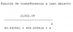
I'm designing a PID control for a BLDC motor, right know I'm working on simulations and the design I'm doing it using scilab, so, I have previously designed the circuit and the transfer function in open loop, also have the transfer function of the system with unit feedback, I have the unit feedback since I'm using Hall sensors to sense the speed of the BLDC motor. Mi original system in open loop is the following

and the unit fieedback system is

the inverse Laplace transform of the unit feedback system is

the time istant to have the tangent line in the inflexion point is t1 = 0.012156 s.
when I realize the study of the system I have the following system responses

The upper left plot is the step response of the system without feedback, this is exactly what I see when I do the simulation of the electrical system.
The upper right plot is the step response of the system with unit feedback and as you can see the response has "S" form which is perfect for using the method 1 of Ziegler-Nichols.
The bottom left plot is the Laplace inverse transform of the unit feedback system, the problem here is as far as I know the inverse Laplace transform which is the Ω(t) and must be equal to the upper right plot but as you can see I don't have the desired plot.
The bottom right plot is supose to be the slope of the step response at every time instant but it can be seen that in the time t1 the value of the slope is almost zero, that doesn't match with the unit feedback with the step response seen at the upper right plot.
So, I need help here to determine if I'm assuming something wrong with the function that I'm using as the inverse Laplace transform to find the slope of the line to design the PID control using Ziegler-Nichols. I've read several documents and chapters related to this theme in mor than one book and I know that I didn't read something somewhere but until now I don't see the wrong criteria that I'm using.
Thanks in advance for the help
I'm designing a PID control for a BLDC motor, right know I'm working on simulations and the design I'm doing it using scilab, so, I have previously designed the circuit and the transfer function in open loop, also have the transfer function of the system with unit feedback, I have the unit feedback since I'm using Hall sensors to sense the speed of the BLDC motor. Mi original system in open loop is the following
and the unit fieedback system is
the inverse Laplace transform of the unit feedback system is
the time istant to have the tangent line in the inflexion point is t1 = 0.012156 s.
when I realize the study of the system I have the following system responses
The upper left plot is the step response of the system without feedback, this is exactly what I see when I do the simulation of the electrical system.
The upper right plot is the step response of the system with unit feedback and as you can see the response has "S" form which is perfect for using the method 1 of Ziegler-Nichols.
The bottom left plot is the Laplace inverse transform of the unit feedback system, the problem here is as far as I know the inverse Laplace transform which is the Ω(t) and must be equal to the upper right plot but as you can see I don't have the desired plot.
The bottom right plot is supose to be the slope of the step response at every time instant but it can be seen that in the time t1 the value of the slope is almost zero, that doesn't match with the unit feedback with the step response seen at the upper right plot.
So, I need help here to determine if I'm assuming something wrong with the function that I'm using as the inverse Laplace transform to find the slope of the line to design the PID control using Ziegler-Nichols. I've read several documents and chapters related to this theme in mor than one book and I know that I didn't read something somewhere but until now I don't see the wrong criteria that I'm using.
Thanks in advance for the help
Attachments
-
 2.5 KB Views: 0


