VFD issues?

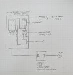
I’m having an issue with a VFD that I’m not seeing when I search all forums. I’ve got a 480V, 3 phase 15hp pit pump that is controlled by a Leeson speed master drive, 25hp capacity. Power is applied through an Allen Bradly starter station with hand/off/auto selector. This pump used to have a float switch and would run automatically, but the environment is too corrosive and would corrode the switch. We’ve been running the starter in hand the last few months, and turning the speed down to about 40hz. A little overflow is of no issue. About a month ago, we had some water get into the starter station and shorted out the starter itself. I replaced it and the overloads and checked everything, everything looked normal. Started the pump and it ran fine for a few minutes and then tripped the overloads on the starter. Ohmed the motor and leads, everything checked good. Started it again, same thing. Amped all 3 phases and I got 11, 0, and 21 amps. Decided to replace the pump and the same thing happened. Replaced the wiring from drive to the pump, same result. Just out of curiosity I took the drive out of the system and everything worked great, same 11 amps on all 3 phases, so we replaced the drive with the exact same type, and problem returned, 0 amps on one of the phases with the overloads tripping on the starter. Any suggestions would be great. I basically only have a clamp on multi meter and hand tools
 
Brent77...
Welcome to Control.com!
The delay between 'start' and 'trip' is understandable, because only 'C phase was at or near the motor's rated capacity!
Q1. How old is system?
Q2. Are you sure that Overload"s" (plural) tripped?
Q3. What are/were Voltage-Ampere-Power readings, with motor operating at 40Hz?
Q4. What are/were Voltage-Ampere-Power readings, with motor operating at 60Hz?
Q5. How is system grounded?
Please provide a Schematic Drawing of the system.
Regards, Phil Corso
 
Brent77...
Welcome to Control.com!
Can you provide a Schematic Drawing of your setup?
Regards, Phil Corso
Thank you! I don’t have a drawing, as this was something we just threw together one day. I can probably make a very crude drawing to give you a better idea of what I’m working with, if you can wait just a bit.
 
And yes, some things they give us drawings for, but most of it is on the fly. I like the diy aspect of it a lot. Keeps me on my toes!
 
Oh and to answer your other questions:
Q1 the system is about 6 years old
Q2 the overload is an electronic overload, so nothing individual
Q3/Q4 I can’t remember right off. I can get those numbers tomorrow
Q5 everything is grounded back to building steel. We just had a contractor come in and do annual ground checks on all equipment with no issues
 
Brent77
My interpretation of your schematic is that you may not have achieved NEC Code requirements, if you are under its jurisdiction! Furthermore, there are people who "squeal" on others for not complying with code-requirements on these publicly available forums!
If you still want to continue, please contact me!
Phil Corso @[email protected]
 
Have a machine where a Linear actuator is controlled by a VFD. VFD is an Omron MX2. looking for a brake holding solution for Actuator is "leaking down". Motor is only a .3kw and vfd .4 kw. Looked at the manual for the MX2 and the Dc braking is only capable fo holding for ma 60 second time. The typical machine cycle is 2-3 minutes.
 
Top